Technical Information
61
CVA 265x & CVA 266x
2 Function
2.1 Appliance Status after a Power Failure
After a power failure, the appliance remains switched off (standby). The fault
memory, as well as all customer settings (except for time of day), remain
unaffected.
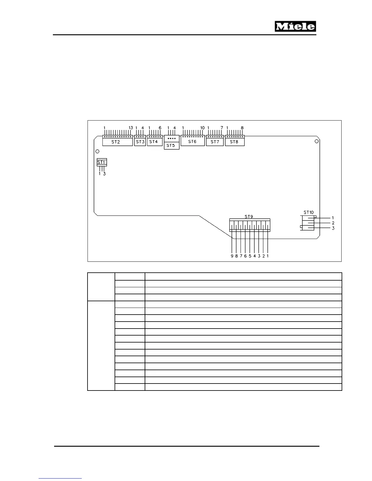
2.2 EPL 85x Power Electronic - Plug and Pin Connections
Figure 060-1: EPL 85x Connectors and Pin Locations
ST 1
Pin Use
1 Contact Spring – Drip Tray Level
2 Contact Spring – Drip Tray Present
3 Contact Spring – Drip Tray (Common)
ST 2
1 Water Tank Switch Contact
2 Water Tank Switch Ground
3 Door Switch Contact
4 Door Switch +5V
5 Capsule Magazine Motor +12V
6 Capsule Magazine Motor –12V
7 Capsule Magazine Optical Sensor +12V (pin 2 on sensor)
8 Capsule Magazine Optical Sensor –12V (pin 4 on sensor)
9 Capsule Magazine Optical Sensor GND (pin 1 on sensor)
10 Capsule Magazine Optical Sensor Output (pin 2 on sensor)
11 Capsule Magazine Motor Switch
12 Capsule Magazine Drawer Switch
13 Capsule Transport Switch