Technical Information
85
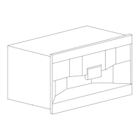
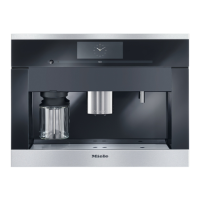
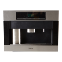
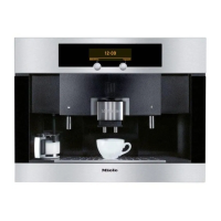
CVA 265x & CVA 266x
Function Option/Component Activated Description
Program index
ID no. 1:
ID no. of display and EPWZ 850
control electronic
ID no. 2:
ID no. of EPL 850 power
electronic
Fault
memory
1
Page 1 Faults 1 - 6
The last 12 fault codes
registered are shown.
The last fault code is marked
with L. If a fault is registered
more than once, its code will be
shown the appropriate number
of times unless the faults
occurred immediately after each
other.
See Table 060-2 for fault code
descriptions.
Page 2 Faults 7 - 12
Component test
Ceramic valve
2
Initialize
Valve reference and
valve position sensors display 0
and 1 alternately.
Step counterclockwise
Step clockwise
Rest position
Coffee position
Water position
Cont. counterclockwise
Continuous clockwise
Capsule transport
2
Initialize Slide sensor reading:
0 = Capsule transport lever in
intermediate setting
1 = Capsule transport lever in
basic setting
Carry out
Service position
Continuous operation
Capsule magazine
2
Initialize
Capsule magazine check
(Table 060-9)
Step counterclockwise
Step clockwise
Chamber 1 to 5
Cont. counterclockwise
Continuous clockwise
Brew unit
2
Initialize To reach the lowered end
position, the capsule plate must
be removed from the brew unit
beforehand.
The press position can only be
reached with the capsule plate
installed.
(See also Table 060-10.)
Rest position
Eject position
Press position
Service position
Continuous upwards
Continuous downwards
Coffee/hot-water pump
Release
The display shows the number
of pulses registered by the flow
meter. See Table 060-11.
Brew unit
Cappuccinatore
Steam pump
Release
Steam pump check
Cappuccinatore