Gas Flow Theory of Operation
1 - 16 046-006272-00 A7™ Service Manual
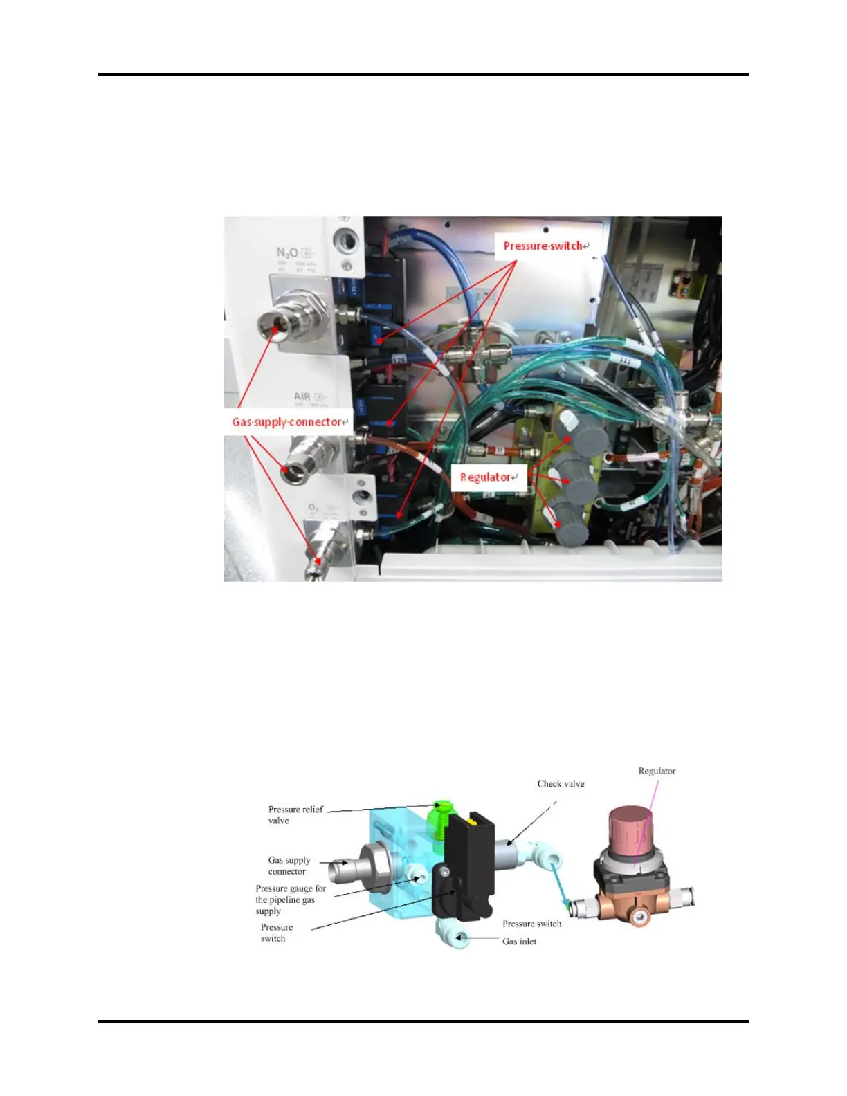
The following figure shows the physical pipeline gas supply inlet assembly of the system, including
the gas supply inlet assembly and regulators. The gas supply inlet assembly integrates the filter,
pressure relief valve, pressure switch and check valve. Gases regulated by the regulator will be output
to the flow control systems EFCS and BFCS.
FIGURE 1-6
The following figure shows the models of the gas supply inlet assembly and regulator. The gas from
the pipeline gas supply (280~600 kPa) enters the system through the gas supply connector. After
being cleaned by the internal filter of the inlet assembly, the gas is output to the regulator and
degraded to about 200 kPa. (The filter can be replaced after the pipeline gas supply connector is
removed).
FIGURE 1-7