A7™ Service Manual 046-006272-00 1 - 17
Theory of Operation Gas Flow
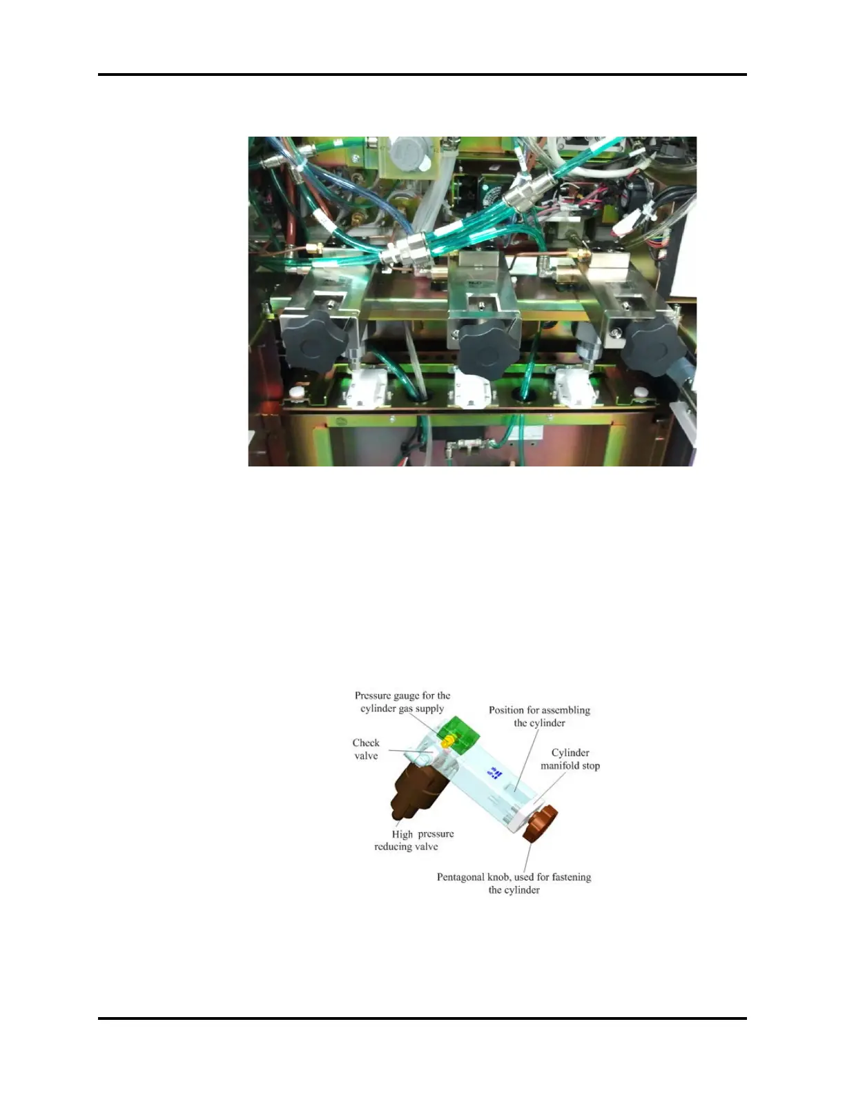
FIGURE 1-8
As shown in the following figure, the gas from the cylinder gas supply is divided into two limbs after
being cleaned by the filter. One limb is directly connected to the high pressure gauge and the other
limb is degraded to 440 kPa by the high pressure reducing valve and then output from the check
valve. After the gas from the cylinder gas supply is mixed with the gas from the pipeline gas supply,
the gas mixture is output to the regulator. Currently, the system provides only a cylinder connector.
The connector complies with CGA V-1. Cylinders of the E size are supported. The capacity of a
cylinder is limited; therefore, it is recommended that the cylinder gas supply is used as the backup
gas supply to prevent gas supply exhaustion.
FIGURE 1-9