A7™ Service Manual 046-006272-00 1 - 27
Theory of Operation Gas Flow
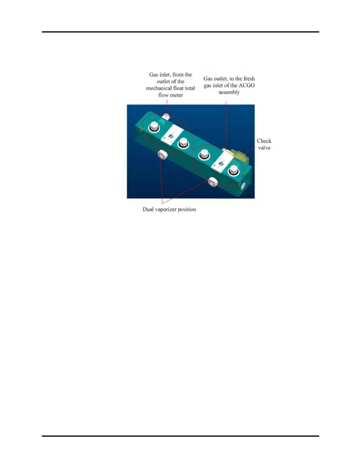
The following figure shows the structure model and the corresponding interface information.
FIGURE 1-24
1.3.4.9 ACGO Assembly
The ACGO assembly is used to connect the fresh gas output from the vaporizer manifold and the O2
output from the O2 flush device to the breathing circuit of the anesthesia machine or to an
independent outlet. Mechanical and electrical ACGO configurations are available.
The electrical ACGO pushes the valve core by gas pressure after switching on the control gas supply
at a corresponding end to switch the ACGO state. The following figure is the diagram. For example,
the status needs to be switched to ACGO OFF. When this order is received, the two drive gas control
valves (two-position three-way solenoid valves in the upper part of the following figure) of the
electrical ACGO switch to the state shown in the following figure. On the left side (as shown in the
green arrows), the two connectors on the left and right of the valve are connected and the gas outlet
in the middle is closed; on the right side (as shown in the black arrows), the connector on the left is
disconnected and the connector on the right and the gas outlet in the middle are connected. In this
case, the drive O2 from the system switch passes through the control valve on the left, outputs to the
main ACGO valve shown at the lower part of the following figure and drives the valve core in the
middle rightwards. At the same time, the residential gas on the left side of the valve core is released
to the air through the drive gas control valve on the right side. If the gas on the right side is not
released, the drive gas on the left side cannot push the valve core. Therefore, the two states must be
available at the same time. The valve core pushes rightwards by the drive gas to implement ACGO
state switching. Then, the fresh gas will be output from the patient circuit outlet of the ACGO
assembly.