Gas Flow Theory of Operation
1 - 30 046-006272-00 A7™ Service Manual
FIGURE 1-29
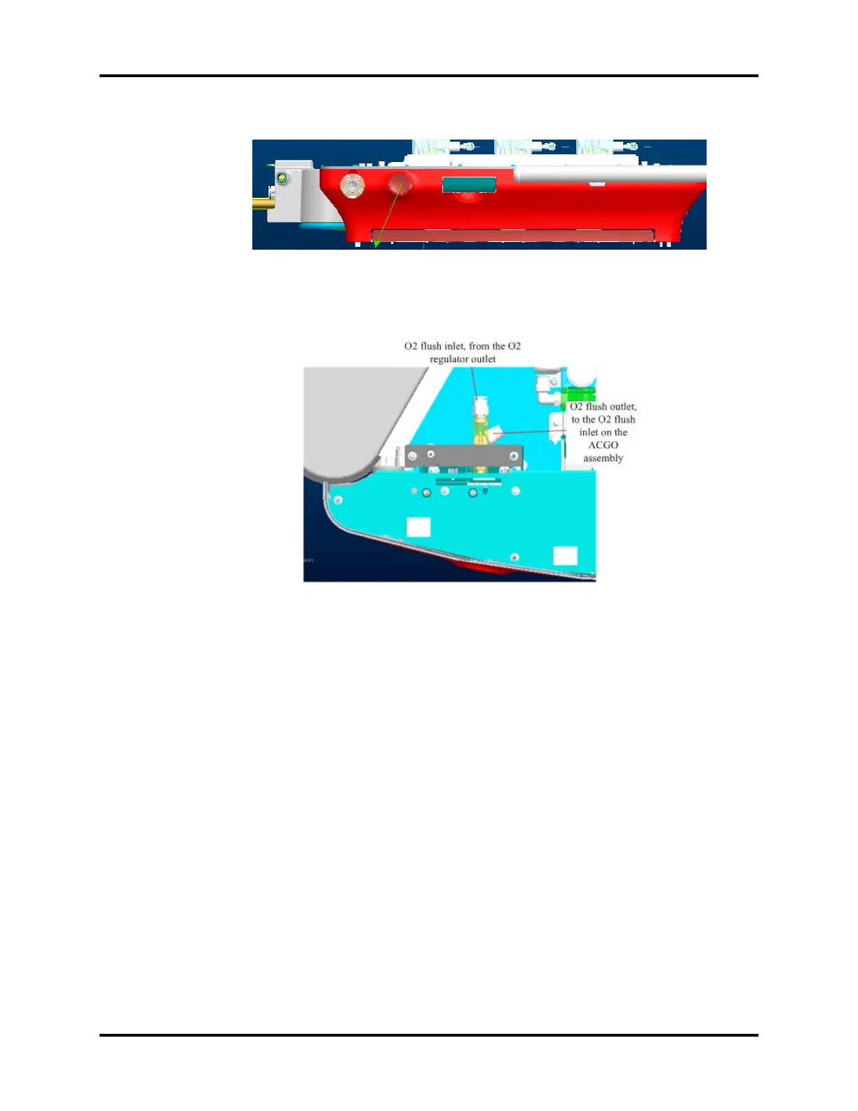
The following figure shows the structure model and the corresponding interface information.
FIGURE 1-30
1.3.4.11 Auxiliary Gas Supply Assembly
The auxiliary gas supply assembly is composed of the oxygen and air limbs. Two needle valves are
used to control the flow of the auxiliary oxygen and air supplies, and corresponding glass tube flow
meters are used for flow monitoring. After being mixed, the oxygen and air are output. The following
figure shows the position of the auxiliary gas supply assembly in the system.