A7™ Service Manual 046-006272-00 1 - 29
Theory of Operation Gas Flow
pendent ACGO outlet. Traditionally, the fresh gas is output from the ACGO limb integrated on the pa-
tient circuit. By contrast, the independent ACGO outlet is independent from the patient circuit. The
following figure shows the position of the independent ACGO outlet in the system. The gas input is
from the ACGO outlet on the ACGO assembly.
FIGURE 1-27
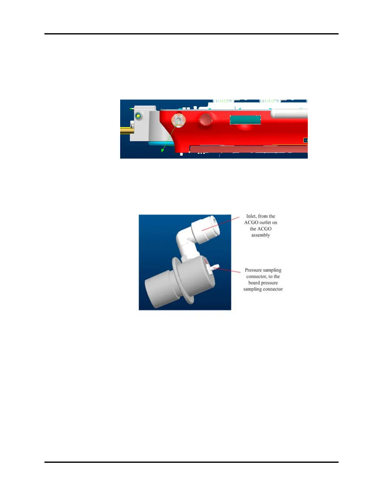
The following figure shows the structure model and the corresponding interface information.
FIGURE 1-28
1.3.4.10 O2 Flush Button Assembly
The O2 flush assembly is located on the work surface. When the O2 flush button is depressed, O2
rushes into the pneumatic circuit, and will be cut off when this button is released. The O2 supply gas
is at 0.2 MPa (29 psi), after being regulated, goes through the O2 flush valve and into the O2 flush inlet
of the ACGO assembly. The O2 flush assembly is not affected by the system switch. Flushing O2 can
be performed as long as O2 supply is normal. The O2 flush valve has a slide valve structure inside that
ensures automatic reset each time the valve is depressed and released via the spring. The following
figure shows the position of the O2 flush valve in the system.