Gas Flow Theory of Operation
1 - 32 046-006272-00 A7™ Service Manual
1.3.4.12 High Pressure O2 Output Assembly
The high pressure O2 input comes from the gas supply (280 to 600 kPa) ( 40 to 87 psi) directly and
provides high pressure O2 for the external ventilation device (jet ventilation devices). See “Auxiliary
Gas Supply Assembly” on page 1-30..
1.3.4.13 Pneumatically-Controlled Module of Anesthetic
The pneumatically-controlled module of the anesthetic ventilator provides drive gas for the patient
to breathe. O2 (or AIR) from the gas supply inlet assembly enters the anesthetic ventilator and is
output in three pathways: drive gas entering the breathing system, drive gas discharged through the
AGSS outlet, and drive gas discharged through the PEEP outlet. The ventilator controls drive gas flow
to implement various ventilation modes and prevent excessively high pressure inside the pneumatic
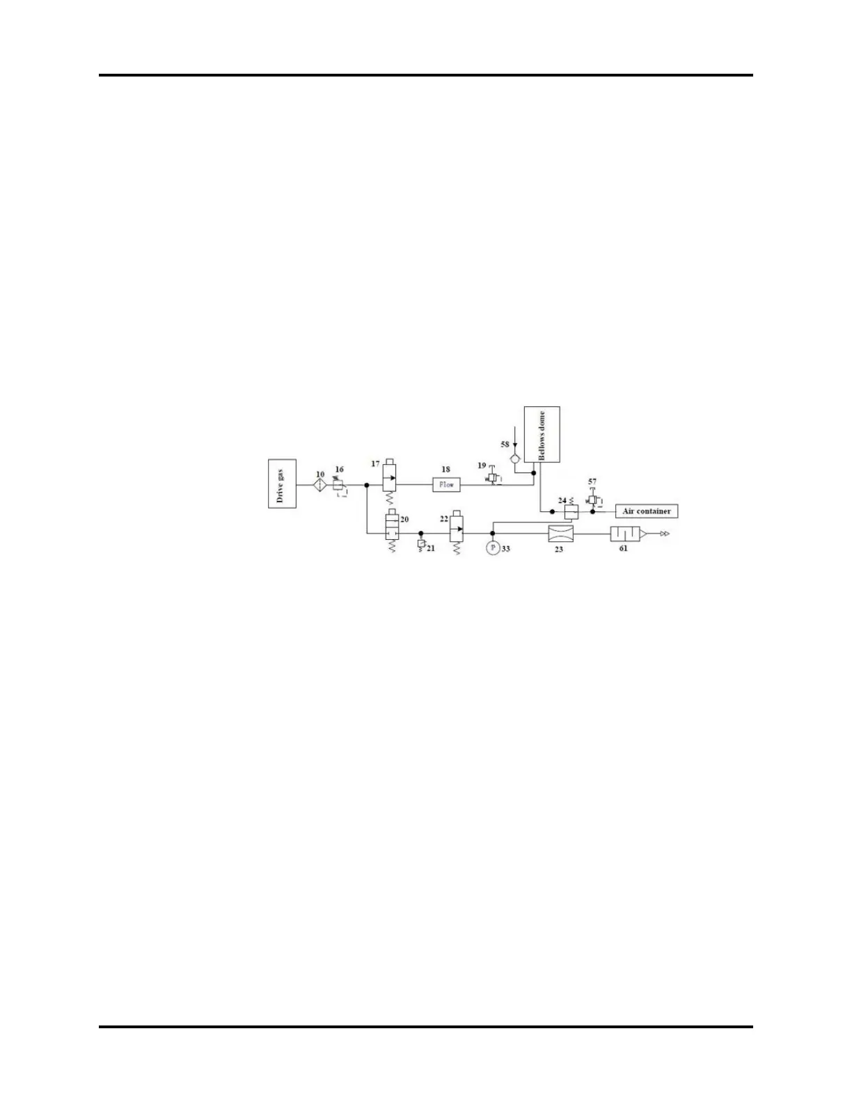
circuit from injuring the patient. The following figure shows the pneumatic circuit diagram of the
anesthetic ventilator.
FIGURE 1-33
As shown in the preceding figure, the filter (10) filters drive gas again. The regulator (16) regulates
pressure (about 0.2 MPa (29 psi)) inside the pneumatic circuit. The proportional solenoid valve (17)
controls the inlet gas flow. Component 18 is a flow sensor of differential pressure type that monitors
gas flow in the drive gas circuit. The mechanical overpressure valve (19) ensures that the pressure in
the drive gas circuit does not exceed the safety pressure. It releases excess gas when gas pressure
exceeds 11 kPa (110 cm H2O). Component 24 is the expiratory valve.
The PEEP function is performed through the expiratory valve. Component 22 is a low-flow
proportional solenoid valve. When it opens, gas is bled from the pneumatic resistor (23), forming
relatively stable pressure in the pneumatic circuit from component 22 to component 23. Such
pressure is exerted on the membrane of the expiratory valve (24) to form PEEP.
To prevent excessively high pressure inside the pneumatic circuit from injuring the patient and
damaging the equipment, the pressure relief valve (20), which is a solenoid on-off valve, is placed
before the gas pathway of the expiratory valve. Component 21 is a pressure switch. When the drive
gas pressure is less than 140 kPa (20.3 psi), an alarm is triggered. Component 33 is a pressure sensor
that monitors the pressure at the expiratory valve which is closed. The mechanical pressure relief
valve (57) ensures that the tube pressure after the expiratory valve is less than 10 cm H2O.
The following figure is a picture of the pneumatically-controlled module of the anesthetic ventilator.