A7™ Service Manual 046-006272-00 1 - 75
Theory of Operation Ventilator Control and Drive
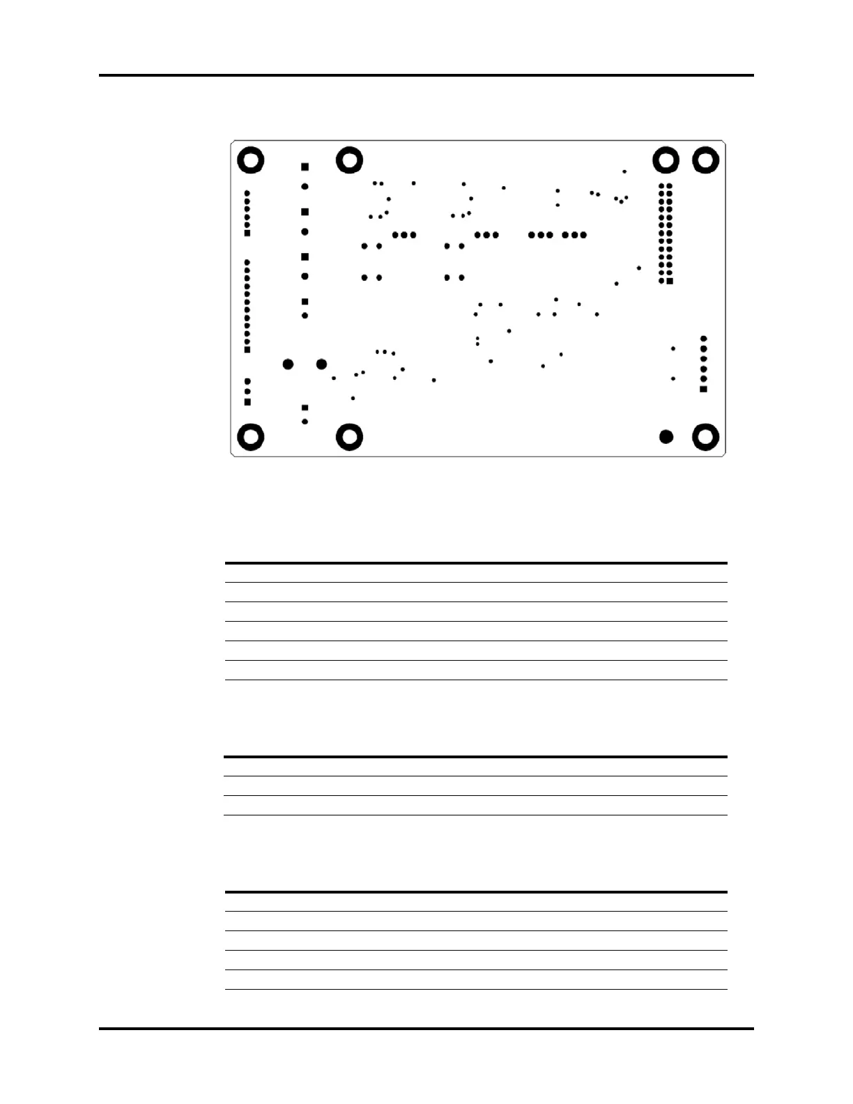
FIGURE 1-76 Valve Drive Board, Bottom View
Proportional Valve and Pressure Relief Valve Drive Interface, J4
Power Supply Interface, J2
Status Monitor Detection Interface, J8
PIN NAME FUNCTION
1 7V Pressure Relief Valve Power Supply
2 SAFE_VALVE Pressure Relief Valve Control Signal
3 7V Inspiration Valve Power Supply
4 INSP_VALVE Inspiration Valve Control Signal
5 7V PEEP Valve Power Supply
6 PEEP_VALVE PEEP Valve Control Signal
PIN NAME FUNCTION
1GND Ground
2GND Ground
3 12V 12V Power Supply
PIN NAME FUNCTION
1GND Ground
2 PNEUM_PRE_SW Circuit block pressure Switch Signal
3GND Ground
4NC /
5GND Ground