Ventilator Control and Drive Theory of Operation
1 - 76 046-006272-00 A7™ Service Manual
Test Point Definition
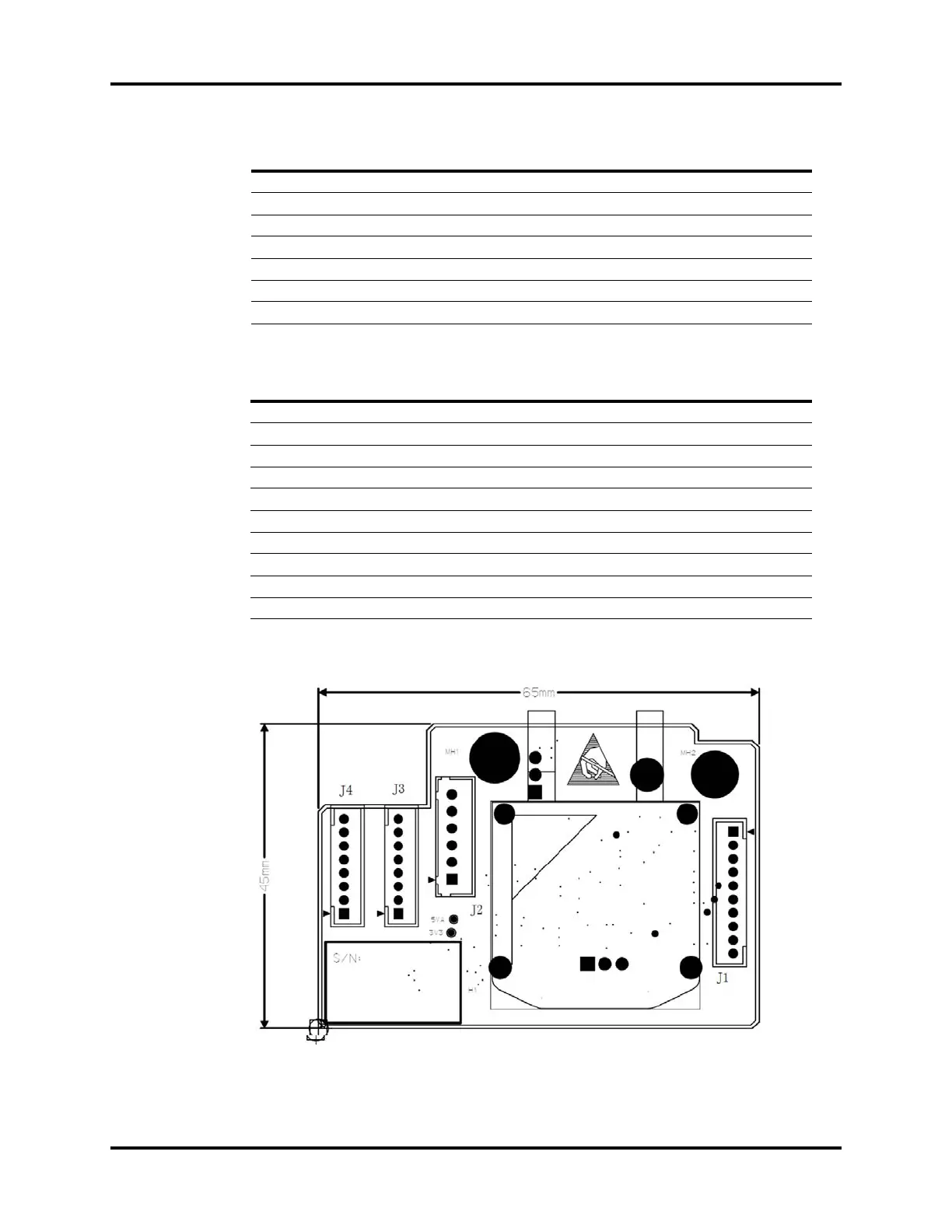
1.7.2.3 Sensor Interface Board
FIGURE 1-77 Sensor Interface Board, Top View
6 QUICK_O2_SW O2 Flushing Pressure Switch Signal
7GND Ground
8 CGO_PRE_SW CGO Switch Signal
9GND Ground
10 O2_PRE_SW O2 Pressure Switch Signal at Gas Supply Inlet
11 GND Ground
12 MANU_AUTO_SW Auto/Manual Switch Signal
DESIGNATOR NAME FUNCTION RANGE (unit: V)
T1 K_OUT1 Status Monitor Signal 0~3.45
T2 K_OUT2 Status Monitor Signal 0~3.45
T3 SAFE Pressure Relief Valve Signal 0~7
T4 VOC Reserved DA Output Signal 0~1.2
T5 AD2 Analog Channel Output Signal 0~5
T6 FLOW Inspiration Valve Control Signal 0~7
T7 PEEP PEEP Valve Control Signal 0~7
T8 10V 12V Input Signal 10~14
T9 7V Valve Power Supply 6.65~7.35
T10 SGND Ground 0
PIN NAME FUNCTION