EasyManua.ls Logo

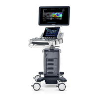
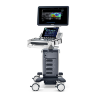
Mindray DC-8

Mindray DC-8
287 pages
To Next Page IconTo Next Page
Loading...
DC-8/DC-8 PRO/DC-8 CV/DC-8 EXP/DC-8S
Diagnostic Ultrasound System
Service Manual
Revision 19.0

Table of Contents

Other manuals for Mindray DC-8

Questions and Answers:

Mindray DC-8 Specifications

General IconGeneral
TypeUltrasound System
Touch PanelYes
Transducer Ports2
Operating SystemWindows-based
Power SupplyAC 100-240V, 50/60Hz
Storage Temperature-20°C to 60°C
Operating Temperature10°C to 40°C
ConnectivityUSB, Ethernet
Imaging ModesDoppler
Power Consumption200 VA
Relative Humidity30% to 75% (non-condensing)
Battery LifeNot applicable
Measurement and AnalysisComprehensive measurement tools

Summary

Intellectual Property Statement

Applicable For

Statement

Responsibility on the Manufacturer Party

Customer Service Department

1 Safety Precautions

1.1 Meaning of Signal Words

Explains the meaning of DANGER, WARNING, CAUTION, and NOTE signal words.

1.2 Safety Symbols and Labels

Provides location and information of safety symbols, warning labels, and general symbols.

1.3 Safety Precautions

Details electric, mechanical, and personnel safety precautions.

2 Specifications

2.1 System Overview

Provides general system overview, intended use, and unit introductions.

2.2 System Specifications Details

Details dimensions, weight, electrical, environmental, and monitor specifications.

3 System Installation

3.1 Preparations for Installation

Covers electrical requirements, EMI limitations, installation conditions, and confirmation.

3.2 Unpacking and Checking

Details unpacking procedures, packing notices, and system checking steps.

3.3 Main Unit Installation

Guides the installation of the main unit, including monitor, power, and ECG connections.

3.4 Installing Peripherals

Covers connecting footswitch, installing printers, and barcode scanners.

3.5 System Configuration

Guides system configuration, presets, network, and DICOM settings.

4 Product Principle

4.1 General Structure of Hardware System

Provides a schematic diagram and overview of the ultrasound system's hardware components.

4.2 Ultrasound Front-end Unit

Details the components and schematic diagram of the ultrasound front-end unit.

4.3 Ultrasound Back-end Unit

Describes the components of the ultrasound back-end unit, including digital board.

4.4 Control Panel Unit

Details the control panel unit, its module composition, and function circuits.

4.5 ECG&PCG Unit

Explains the ECG&PCG unit, its function, and connection structure.

4.6 Main Monitor Unit

Describes the main monitor unit's components and function.

4.7 Touch Screen Unit

Details the touch screen unit's components and function.

4.8 Power Supply Unit

Explains the power supply unit's components and function distribution.

5 Function and Performance Checking Method

5.1 Note

Provides a note regarding the detailed method for function and performance checking.

5.2 System Running Status

Describes how to check the system's running status and working conditions.

5.3 General Exam Checks

Details the general exam check flow and content for various system components.

5.4 Function Checking

Details function checking procedures for imaging modes, basic measurements, and cine review.

5.5 Performance Test

Covers performance test processes, content, and specific tests like resolution and depth.

6 Software Installation &Maintenance

6.1 Enter into Maintenance

Guides how to log in as Service and access the maintenance menu for operations.

6.2 Software InstallationRestoration

Refers to the system recovery guide for details on software installation and restoration.

6.3 Enter into Windows

Explains how to obtain a password and enter the Windows operating system.

6.4 Software Maintenance

Covers product configuration, log maintenance, and remote desktop operations.

6.5 Data Backup and Storage

Details how to back up and restore preset data and patient data.

6.6 HDD Partition

Provides details on HDD capacity and data distribution across drives.

7 Adjustments

7.1 Monitor Adjustment

Covers monitor position, brightness, contrast adjustments, and testing.

7.2 Touch Screen Adjustment

Guides on adjusting touch screen brightness, contrast, and calibration.

7.3 Control Panel Adjustment

Covers control panel position and key backlight brightness adjustments.

7.4 Caster Adjustment

Details how to lock and release the system's casters for stability.

8 Field Replaceable Unit

8.1 Receiving Board

Lists the Receiving Board as a spare part, its order number, and compatibility.

8.2 Transmission Board

Lists the Transmission Board as a spare part, its order number, and compatibility.

8.3 DSP Board

Lists the DSP Board (NO 4D&EI Module) as a spare part and its compatibility.

8.4 PC Assembly

Details PC assembly variants for DC-8 EXP and non-EXP models with different OS.

8.5 CPU Module

Lists the CPU Module as a spare part, its order number, and compatibility.

8.6 Digital Board Assembly

Lists Digital Board Assembly variants (FRU) for different models and OS.

8.7 COM Module

Lists the COM module (DC-8 EXP/FRU) as a spare part and its compatibility.

8.8 Probe Board Assembly

Lists the Probe Board Assembly (FRU/cost-down rack) as a spare part and its compatibility.

8.9 HDD Assembly

Lists HDD Assembly (spare part) variants for different models and OS.

8.10 IO BOX Board

Lists the IO BOX Board (spare part) and its compatibility, with and without WiFi.

8.11 WIFI Module

Lists the WIFI module as an optional hardware component.

8.12 Communication Mother Board

Lists the Communication Mother Board Assembly (spare part).

8.13 Front-end Analog Mother Board

Lists the Front-end Analog Mother Board as a spare part.

8.14 Back-end Mother Board

Lists the Back-end Mother Board as a spare part.

8.15 Connecting Board

Lists the 2120 Connecting Board (spare part) and its compatibility.

8.16 AC-DC Assembly

Lists the 2120 AC-DC Assembly (spare part) and its compatibility.

8.17 Back-end Power Board

Lists the 2120 Back-end Power Board (spare part) and its compatibility.

8.18 Front-end Power Main Board

Lists the 2120 Front-end Power Main Board (spare part) and its compatibility.

8.19 Front-end Power Auxiliary Board

Lists the 2120 Front-end Power Auxiliary Board (spare part) and its compatibility.

8.20 Top Cover of Keyboard Assembly

Lists the Top Cover of Keyboard Assembly (spare part) for different models.

8.21 Minor Panel Assembly

Lists the Minor Panel Assembly as a spare part for DC-8 EXP.

8.22 EXP Control Panel Top Cover

Lists the EXP control panel top cover as a spare part for DC-8 EXP.

8.23 Digital Keyboard Module

Lists Digital Keyboard Module (spare part) for various models and software versions.

8.24 Master Panel Six in One Encoder Assembly

Lists the Master panel six in one encoder Assembly (spare part).

8.25 NAVI-Encoder Assembly

Lists the NAVI-Encoder Assembly (spare part).

8.26 ZOOM Encoder Assembly

Lists the ZOOM Encoder Assembly (spare part).

8.27 TGC Assembly

Lists the TGC Assembly (spare part).

8.28 Trackball Assembly

Lists the Trackball Assembly (spare part).

8.29 Trackball Key Board

Lists the Trackball Key Board.

8.30 10.4 Inch Monitor Assembly

Lists the 10.4 Inch Monitor Assembly (spare part).

8.31 Touch Screen Assembly

Lists the Touch Screen Assembly (spare part).

8.32 Minor Control Key Board Assembly

Lists the Minor Control Key Board Assembly (spare part).

8.33 Minor Control Six in One Encoder Assembly

Lists the Minor Control six in one encoder Assembly (spare part).

8.34 Signal Speaker Assembly

Lists the Signal Speaker assembly (spare part).

8.35 USB Adapter Board

Lists the USB adapter board on the control panel.

8.36 Control Panel Silica Key

Lists the Control Panel Silica Key.

8.37 Left Silica Key

Lists the Left Silica Key.

8.38 Right Silica Key

Lists the Right Silica Key.

8.39 Control Panel Silica Key 1

Lists the Control Panel Silica Key 1.

8.40 Power Silica Key

Lists the Power Silica Key and its location.

8.41 Buzzer Connecting Cable

Lists the Buzzer Connecting Cable.

8.42 Monitor Assembly

Lists 21.5 inch and 23.8 inch Monitor Assemblies (spare part/FRU).

8.43 Fan Related Assemblies

Lists Small and Big Fans assemblies (spare part) and their quantity.

8.44 Accessories Case Components

Lists Endocavity probe holder and Pencil probe holder from the accessories case.

8.45 Probe Holders

Lists Probe holder (deep) and Probe holder (small & shallow).

8.47 Touch Pen

Lists the Touch pen (mould MR62422).

8.48 DVD-RW

Lists the DVD-R/W module (with SATA port and white cover).

8.49 Gas Spring Assembly

Lists the Gas spring assembly (FRU/cost-down rack).

9 Structure and AssemblyDisassembly

9.1 Structure of the Whole System

Provides an overview of the entire system's structure.

9.2 Preparation for AssemblyDisassembly

Details required tools, engineer qualifications, and necessary preparations before disassembly.

9.3 Assembly and Disassembly Procedures

Describes the disassembly and assembly procedures for main assemblies and boards.

9.3.1 Connecting Board

Details the procedure for connecting the power input assembly.

9.3.2 Remove Probe Board Assembly

Guides the removal of the probe board assembly and related components.

9.3.3 Hard Disk Assembly

Provides notes and steps for disassembling and assembling the hard disk.

9.3.4 IO BOX Board and WIFI PCBA

Guides the removal of the IO BOX board, WIFI PCBA, and related components.

9.3.5 Board AssemblyDisassembly

Details the disassembly/assembly of CW, Transmission, Receiving, DSP, and 4D/4D&TEE boards.

9.3.6 PC Module Assembly

Guides the removal and installation of the PC module assembly.

9.3.6.1 Digital Board Assembly and COME Module (Win7)

Details assembly of Digital Board and COME module for Win7 systems.

9.3.6.2 DVR Board

Guides the removal and installation of the DVR board.

9.3.7 DC-DC Power Module

Guides the disassembly and assembly of the DC-DC Power Module and its boards.

9.3.8 AC-DC Power Board

Guides the removal and installation of the AC-DC Power Board.

9.3.9 Control Panel Assembly

Guides the assembly and disassembly of the control panel.

9.3.10 Monitor Assembly

Covers monitor assembly, back cover removal, and front cover replacement.

9.3.11 Minor Panel Assembly

Guides the removal of the minor panel assembly and its back cover.

9.3.11.1 10.4 inch Display Assembly

Guides the removal of the 10.4 inch display assembly and touch screen wire.

9.3.11.2 10.4 inch LCD Screen Control Board

Guides the removal of the 10.4 inch LCD Screen Control Board.

9.3.11.3 Touch Screen Module

Guides the removal and installation of the touch screen module.

9.3.11.4 Minor Panel Six in One Encoder Module

Guides the removal of the six in one encoder module from the minor panel.

9.3.11.5 Minor Keyboard Module and Power Silicon Key

Guides the removal of the Keyboard and power silicon keypad assembly.

9.3.12 Others

Covers other components like fans, DVD-R/W, and speaker assembly.

9.3.12.1 Fan Assembly

Guides the removal and installation of air outlet and air inlet fans.

9.3.12.2 DVD-RW

Guides the removal and installation of the DVD-R/W module.

9.3.12.3 Speaker Assembly

Guides the removal and installation of the speaker assemblies.

9.3.12.4 Gas Spring Assembly Disassembly

Details the procedure for disassembling the gas spring assembly.

9.3.12.5 Install Gas Spring Assembly

Guides the installation process for a new gas spring assembly.

10 Optional InstallationAssembly

10.1 Installing Optional Software

Guides copying key files, selecting software, and managing trial/promotion options.

10.1.1 Uninstalling Optional Software

Details the process for uninstalling optional software packages from the system.

10.2 Installing Optional Hardware

Lists optional hardware components with part numbers, photos, and assembly sections.

10.2.1 Front Board USB&ECG and Pencil Probe Port Assembly

Guides the installation of the front board USB, ECG, and pencil probe ports assembly.

10.2.2 4 D Module

Guides the installation of 4D or 4D&TEE board and Signal Processing Board for 4D function.

10.2.3 Elastography

Guides the installation of Elastography, including replacing the signal processing board.

10.2.4 CW Board

Guides the installation of the CW board.

10.2.5 DVR Board

Guides the installation of the DVR board.

10.2.6 Battery Assembly

Guides the installation of the battery assembly.

10.2.7 Gel Warmer

Details how to assemble and connect the gel warmer.

10.2.8 WIFI Module Update

Provides a chart for updating the WIFI module process.

11 System Diagnosis and Support

11.1 General Status Indicators

Describes status indicators for power, battery, AC, standby, and hard disk on the control panel.

11.1.2 Power Status Indicators

Details status indicators for digital board power supplies (D+12V, D+5V, D+3V3).

11.1.3 Monitor Status Indicator

Describes the monitor status indicator and its meaning.

11.1.4 Machine Status Indicators

Explains the status indicators for scanning, freezing, standby, and screen-save modes.

11.1.5 Gel Warmer Status Indicator

Describes the status indicator for the ultrasound gel warmer.

11.2 System Start-up Process

Illustrates the system start-up sequence and AC power on process.

11.2.1 Complete System AC Power On Process

Details the steps and status during the complete system AC power on process.

11.2.2 BIOS Start-up Process

Describes the basic process and status definitions for BIOS start-up.

11.2.3 Windows Start-up Process

Outlines the basic processes and status definitions for Windows start-up.

11.2.4 Doppler Start-up Process

Details the start-up process for the Doppler application.

11.3 Warning and Abnormal Information

Lists and explains various warning and abnormal alarms, including battery, voltage, and temperature alerts.

11.3.4 Fan Alarm

Details fan alerts, current speed, limit speed, and fan names.

11.3.5 PHV Alarm

Explains PHV alarms, log records, and potential reasons for high-voltage issues.

11.3.6 Gel Warmer Abnormality

Describes potential causes and suggestions for gel warmer abnormalities.

11.3.7 Other Alarms

Lists other alarms, such as configuration errors and ADT7462 initialization issues.

11.4 Self-test

Introduces self-test types and describes maintenance self-test procedures.

11.4.2 Maintenance Self-test

Guides entering the maintenance self-test interface and configuring test items.

11.4.3 User Self-test

Describes the user self-test screen, its regions, and button functions.

11.4.4 Test Report

Explains test forms, test results display, and saving/shutting down the system.

12 Care & Maintenance

12.1 Overview

Recommends procedures for care and maintenance, listing tools and consumables.

12.2 Cleaning the System

Provides a flow and content for cleaning the system, including dust-proof covers and monitors.

12.3 Checking

Covers general checks, system function checks, and peripheral/options checks.

12.3.4 Mechanical Safety Inspection

Details mechanical safety inspection for casters, handle, monitor, and other mechanics.

12.3.5 Electrical Safety Inspection

Refers to Appendix A for electrical safety inspection details.

13 Troubleshooting of Regular Malfunctions

13.1 Troubleshooting Power Issues

Addresses issues when the system cannot be powered on, including module/board checks and key points.

13.2 Troubleshooting Startup Issues

Covers issues when the system cannot be started up, including module/board and key point troubleshooting.

13.3 Troubleshooting Image Display Issues

Addresses problems with image display, including module/board and key point troubleshooting.

13.4 Probe Socket System Troubleshooting

Covers module/board issues, key points, and troubleshooting for probe socket malfunctions.

13.5 IO System Troubleshooting

Addresses module/board issues, key points, and troubleshooting for IO system malfunctions.

13.6 Control Panel Malfunction Troubleshooting

Covers module/board issues and key points for control panel malfunctions.

13.7 LCD and Display Malfunction Troubleshooting

Addresses module/board issues, key points, and troubleshooting for LCD/display malfunctions.

13.8 ECG Module Troubleshooting

Covers module/board issues, key points, and troubleshooting for ECG module malfunctions.

Appendix A Electrical Safety Inspection

A.1 Power Cord Plug Inspection

Details the inspection procedure for the power cord plug, body, strain relief, and connections.

A.2 Device Enclosure and Accessories Inspection

Covers visual and contextual inspection of the device enclosure and accessories for damage or anomalies.

A.3 Device Labeling Inspection

Details the check for manufacturer labels on the main unit, warning labels, and caution labels.

A.4 Protective Earth Resistance Test

Guides the preparation and execution of the protective earth resistance test using a safety analyzer.

A.5 Earth Leakage Test

Details the procedure for performing the earth leakage test on the device.

A.6 Patient Leakage Current Test

Guides the preparation and performance of the patient leakage current test.

A.7 Mains on Applied Part Leakage Test

Details the procedure for testing mains voltage on applied part leakage.

A.8 Patient Auxiliary Current Test

Guides the preparation and performance of the patient auxiliary current test.

Appendix B Phantom Usage Illustration

Phantom KS107 BD Target Disposal

Illustrates the target disposal for the KS107BD phantom, including axial, lateral, and blind-area targets.

Phantom KS107 BG Target Disposal

Illustrates the target disposal for the KS107BG phantom, including axial, lateral, and longitudinal targets.

Appendix C Self-diagnosis Test Items

C.1.1 Z0101 Hard Disk Verify

Describes the process and suggestions for verifying hard disk files and data.

C.1.2 Z0201 PC Module Heat Sink Test

Explains how to test the PC module heat sink installation and monitor CPU temperature.

C.1.3 PC Module and MF FPGA Interconnection Test

Tests LPC communication between PC module and MF FPGA, suggesting digital board replacement if failed.

C.1.4 SVIDEO Buffer DDRII Test

Tests if SVIDEO DDR II works normally, suggesting digital board replacement if failed.

C.1.5 MF FPGA and System Monitor Interconnection Test

Tests SMBUS communication and suggests digital board replacement if failed.

C.1.6 Fan Speed Monitor Test

Tests if the system fans work normally and rotate speed is within limits.

C.1.7 System Temperature Test

Monitors if the main configured boards temperatures are normal.

C.1.8 System Voltage Test

Monitors system board voltages and suggests replacing the button battery or boards with abnormal voltage.

C.1.9 Speaker Test

Tests the audio chip, power amplification circuit, and speaker functions.

C.1.11 Serial Port Test

Checks if the serial port of IO BOX board works normally, suggesting IO BOX board replacement if failed.

C.1.12 Microphone Interface Test

Tests the microphone interface, suggesting digital board replacement if failed.

C.1.13 MF and Front Power Main Board ARM Interconnection Test

Tests communication serial port between MF FPGA and Front-end power ARM, suggesting board replacement if failed.

C.1.14 Front Power Main Board Function Test

Tests output of high voltage and PHV setting, suggesting board replacement if failed.

C.1.15 MF and Back-End Power ARM Interconnection Test

Tests communication serial port between MF FPGA and Back-end power ARM, suggesting board replacement if failed.

C.1.16 Battery I2 C Interconnection Test

Checks I2C communication between battery and back-end power management ARM, suggesting back-end board replacement if failed.

C.1.17 LCD Monitor I2 C Connection Test

Checks I2C communication between FPGA and LCD monitor, suggesting digital board change if failed.

C.1.18 Touch Screen LCD Monitor I2 C Connection Test

Checks I2C communication between FPGA and touch screen LCD, suggesting digital board change if failed.

C.1.19 Keyboard USB Interconnection Test

Tests keyboard and USB port communication, suggesting keyboard or digital board change if failed.

C.1.20 Keyboard Key, Encoder, TGC, Trackball Function Test

Tests keyboard buttons, encoders, TGCs, trackball, and LEDs, checking board ID and FPGA.

C.1.21 Keyboard Key and Trackball LED Test

Tests keyboard button and trackball LEDs, suggesting board change if failed.

C.1.22 PC Module and DSP Interconnection Test

Tests PCIeX4 BUS between PC module and DSP, suggesting DSP board replacement if failed.

C.1.23 DSP DDR Test

Tests DDR loading function of DSP FPGA, suggesting board replacement if failed.

C.1.24 Transmitter Board A Slot ID Test

Checks if transmitter board A is in place, suggesting transmission board replacement if failed.

C.1.25 Transmitter Board A and DSP Board Interconnection Test

Tests connectivity between transmitter board A and DSP board, suggesting board replacement if failed.

C.1.26 Transmitter Board B Slot ID Test

Checks if transmitter board B is in place, suggesting transmission board replacement if failed.

C.1.27 Transmitter Board Band DSP Board Interconnection Test

Tests connectivity between transmitter board B and DSP board, suggesting board replacement if failed.

C.1.28 BF1 FPGA and DSP FPGA Interconnection Test

Tests control BUS connectivity between DSP and BF1 FPGA, suggesting receiving board replacement if failed.

C.1.29 BF1 FPGA and BF2 FPGA Interconnection Test

Tests control BUS connectivity between BF1 FPGA and BF2 FPGA, suggesting receiving board replacement if failed.

C.1.30 BF and DSP Interconnection Test (Data Interface)

Tests data BUS connectivity between DSP and BF1/BF2 FPGA, suggesting receiving board replacement if failed.

C.1.31 ATGC Function Test

Tests ATGC gain function, suggesting receiving board replacement if malfunction.

C.1.32 AFE Digital Interface Test

Tests AFE chip function on CW board, suggesting receiving board replacement if failed.

C.1.33 Transmission and Reception Function Test

Tests 128 channels between transmission and receiving, suggesting receiving or transmission board replacement.

C.1.34 Probe Board and Receiver Board Interconnection Test

Tests SPI control BUS between probe and receiver boards, suggesting probe board replacement if failed.

C.1.35 CW Board and DSP Board Interconnection Test

Tests control BUS between DSP and CW FPGA, suggesting board replacement.

C.1.36 CW and DSP Interconnection Test (Data Interface)

Tests data BUS between DSP and CW FPGA, suggesting CW or DSP board replacement.

C.1.37 CW SPI Test

Tests SPI BUS between CW FPGA and AFE, suggesting CW board replacement.

C.1.38 CW AFE Digital Interface Test

Tests AFE function on CW board, suggesting CW board replacement if failed.

C.1.39 CW ATGC Function Test

Tests ATGC gain function on CW board, suggesting CW board replacement if malfunction.

C.1.40 CW IQ Test

Tests I and Q route functions on CW board, suggesting CW board replacement if failed.

C.1.41 4 D Driver Board ID Test

Checks if 4D board is in place and reads its ID and logic version.

C.1.42 4 D Driver Board Driver Circuit Test

Tests driver circuits of the 4D board, suggesting board replacement if malfunction.

C.1.43 4 D Driver Board Programmable Voltage Test

Tests programmable voltage output of the 4D board, suggesting board replacement if failed.

C.1.44 ECG Module Information Read Test

Checks ECG board presence and reads its ID, logic, and software versions.

C.1.45 ECG Module Self Test

Checks ECG board presence and performs self-test, suggesting ECG board replacement if failed.

Related product manuals