3-12 System Preparation
When connecting a USB memory device to the ultrasound system via a USB port, you can hear a
sound if it is connected successfully and the icon will appear in the lower right corner of the
screen.
To remove the USB memory device: Click the icon to open the [Remove USB Device] screen.
Select the memory device to be removed. Click [OK] and you can hear a sound. Remove the USB
memory device. A sound is heard when removing the USB memory device.
The diagnostic ultrasound system supports USB 3.0.
3.6.2 Connecting a Footswitch
WARNING:
Do not connect two or more footswitches to the main unit;
otherwise, it may lead to the malfunction to the system.
The system supports the wired footswitch of USB port type.
Connection
Directly insert the USB port of the footswitch to the system applicable USB ports.
Function Setting
The function of the footswitch can be preset, for details, please refer to Chapter “12.1.7
iConsole&Footswitch”
3.6.3 Installing a Graph/Text Printer
Add a local printer
NOTE: Unless otherwise specified, printers listed in Chapter 0
Peripherals Supported have drivers installed already.
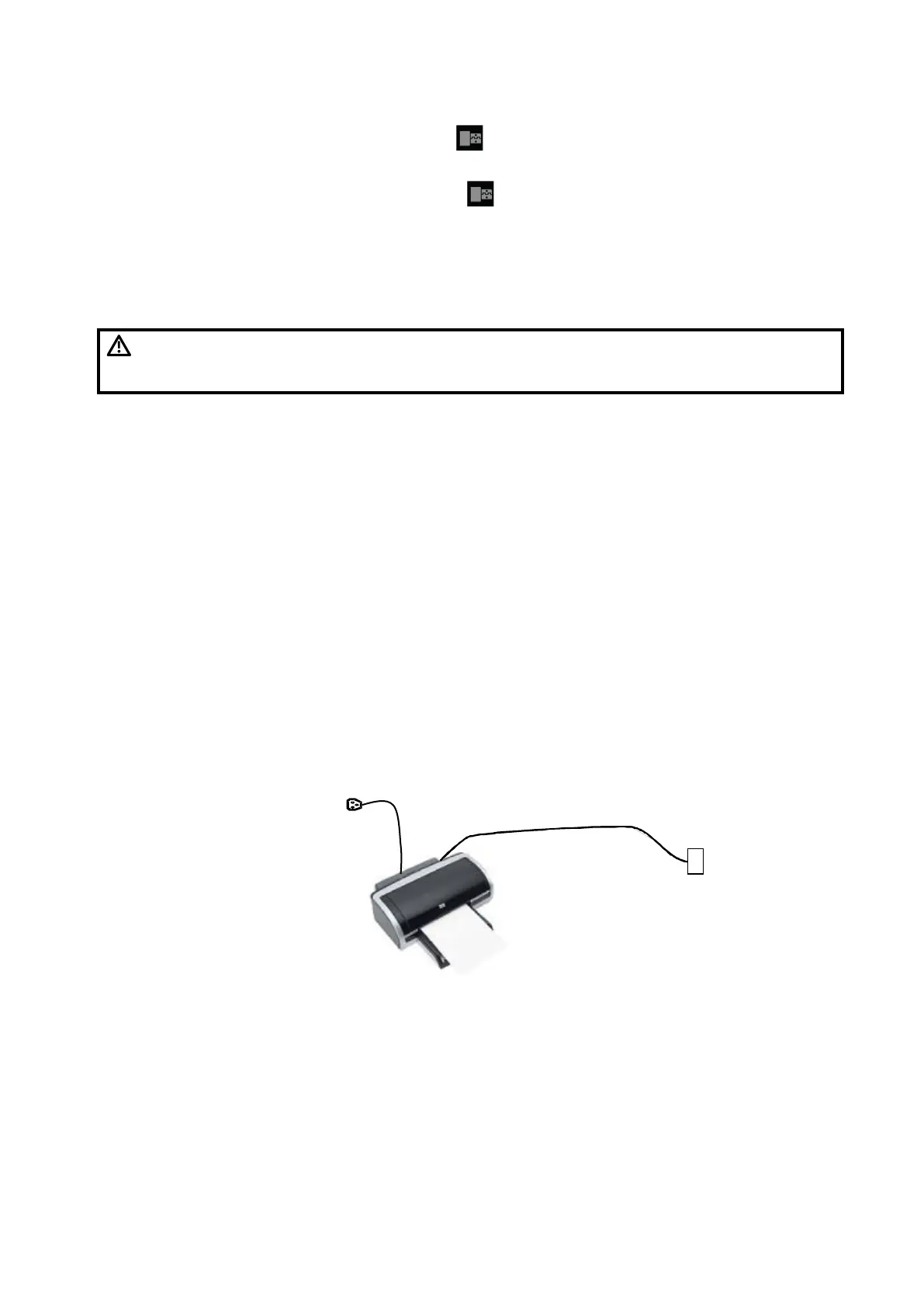
As shown in the figure below, a graph/text printer has a power cord and data cable. The power cord
shall be directly connected to a wall receptacle as required.
1. Connect the data cable to USB port of the ultrasound device.
2. Power on the system and the printer.
3. Install the printer driver. For details, please contact the Mindray service engineer.
Print
Both report and image can be printed on a graph/text printer.
Set the default report printer and its attribute:
Data cable
USB port
Power supply cable
 Loading...


