10. Interface specifications
MiR500 User guide (en) 09/2019 - v.1.3 ©Copyright 2018-2020: Mobile Industrial Robots A/S. 138
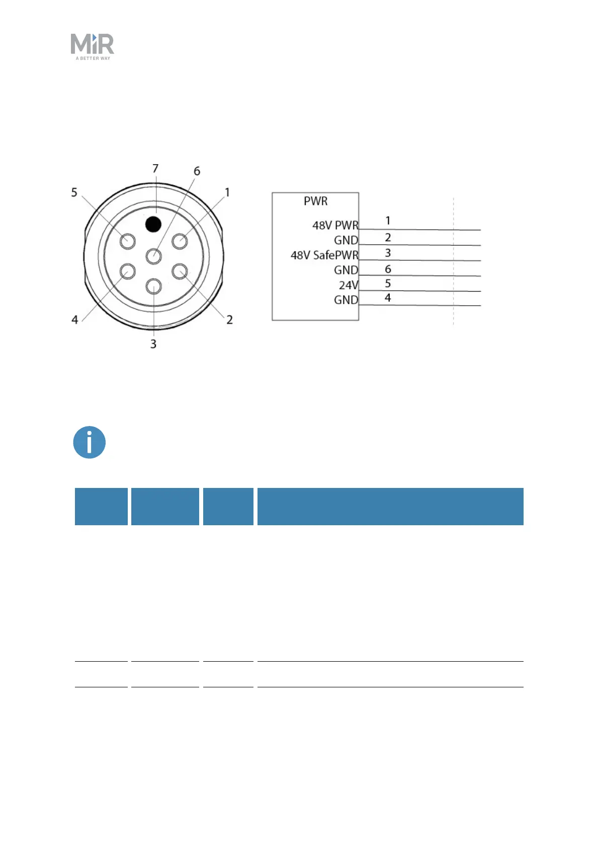
Power
An auxiliary power connection for top applications is provided in the top left-hand side
compartment. See Connector list on page148 for more information.
Figure 10.1. Pin numbers: female connector viewed from the front (left) and wiring diagram (right).
The following table contains the description of the pins of the Power interface.
The maximum current across pins 1 and 3 combined is 20A. You cannot
receive 20Afrom both of them at the same time.
Pin
number
Signal
name
Max.
current
Description
1 48V power 20A Turns off in case of a protective or emergency stop,
via a transistor in the power board.
There are no additional safety precautions taken
with this power output. For this reason, it is
recommended to use the power output from pin 3
instead.
Intended for high power loads like motors or
actuators.
2 GND Ground.