10. Interface specifications
MiR500 User guide (en) 09/2019 - v.1.3 ©Copyright 2018-2020: Mobile Industrial Robots A/S. 148
Pin num-
ber
Signal name Description
14 Unassigned Unassigned.
15 Safe RTN Safe return - Ground.
16 Unassigned Unassigned.
17 Unassigned Unassigned.
10.3 Connector list
We recommend the following connectors for the five different interfaces.
Connector name Connector type Phoenix Contact
Dimension draw-
ing
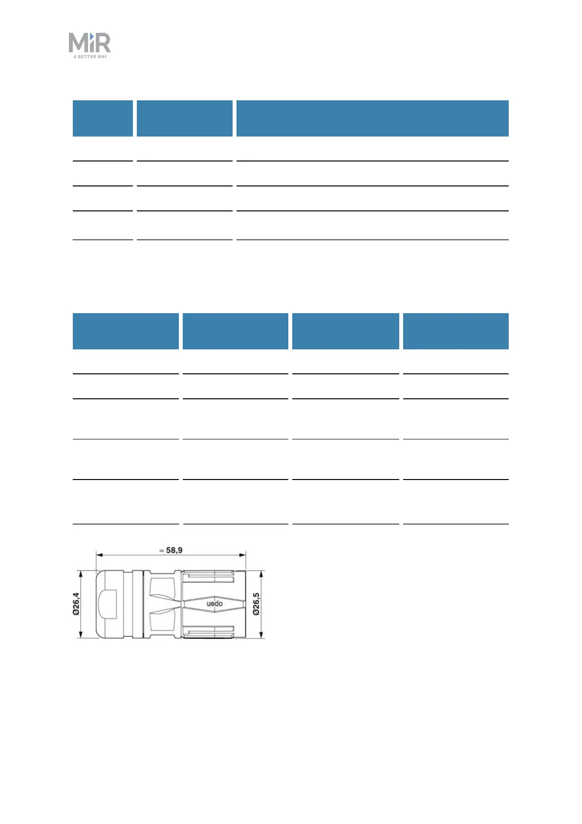
Power M23 6p CA-06P1N8A8008S See Figure 10.8.
GPIO M17 17p ST-17S1N8A8K03S See Figure 10.9.
Ethernet M12 4p SACC-MSD-4PCT-SH
PN SCO
Auxiliary Emer-
gency Stop
M17 8p ST-08P1N8A8K03S See Figure 10.9.
Auxiliary Safety
Functions
M17 17p ST-17P1N8A8K03S See Figure 10.9.
Figure 10.8. Connector dimensions for Power connector.