10. Interface specifications
MiR500 User guide (en) 09/2019 - v.1.3 ©Copyright 2018-2020: Mobile Industrial Robots A/S. 147
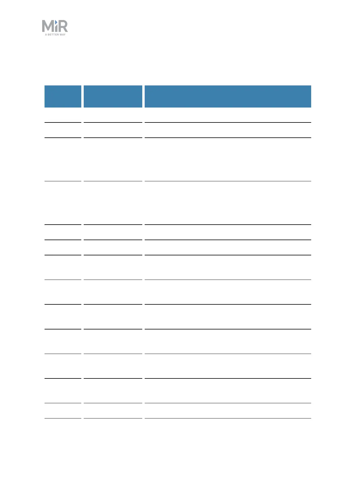
The following table contains the description of the pins of the Auxiliary safety functions
interface.
Pin num-
ber
Signal name Description
1 Test output 24V out.
2 Test output 24V out.
3 Safeguarded stop
1
Safeguard dual channel input. Set any or both pin(s)
low to enter Emergency stop. If pins are unequally set
for a period greater than 3 seconds, PLC will have to
be reset by setting both pins LOW, then high.
4 Safeguarded stop
2
Safeguard dual channel input. Set any or both pin(s)
low to enter Emergency stop. If pins are unequally set
for a period greater than 3 seconds, PLC will have to
be reset by setting both pins LOW, then high.
5 Locomotion 1 Output - high when the robot is standing still.
6 Locomotion 2 Output - high when the robot is standing still.
7 Shared E-stop out
1
Shared emergency stop out 1. Output - low when the
robot is in protective stop.
8 Shared E-stop out
2
Shared emergency stop out 2. Output - low when the
robot is in protective stop.
9 Shared E-stop in
1
Shared emergency stop in 1. Input - Low = robot goes
to protective stop.
10 Shared E-stop in
2
Shared emergency stop in 2. Input - Low = robot goes
to protective stop.
11 Reduced speed 1 Input - circuit broken will result in that the robot can
not drive fast.
12 Reduced speed 2 Input - circuit broken will result in that the robot can
not drive fast.
13 Unassigned Unassigned.