10. Interface specifications
MiR500 User guide (en) 09/2019 - v.1.3 ©Copyright 2018-2020: Mobile Industrial Robots A/S. 146
Pin
number
Signal
name
Description
3 E-stop 1 Output signal 1 to safety PLC for emergency
stop circuit. Should connect to pin 1.
4 E-stop 2 Output signal 2 to safety PLC for emergency
stop circuit. Should connect to pin 2.
5 Reset When high, the robot restarts.
6 Safe RTN Safe return.
7 Reset lamp Only available in MiR500 U0277 and
MiR1000 V0036 and higher.
8 Unassigned Unassigned.
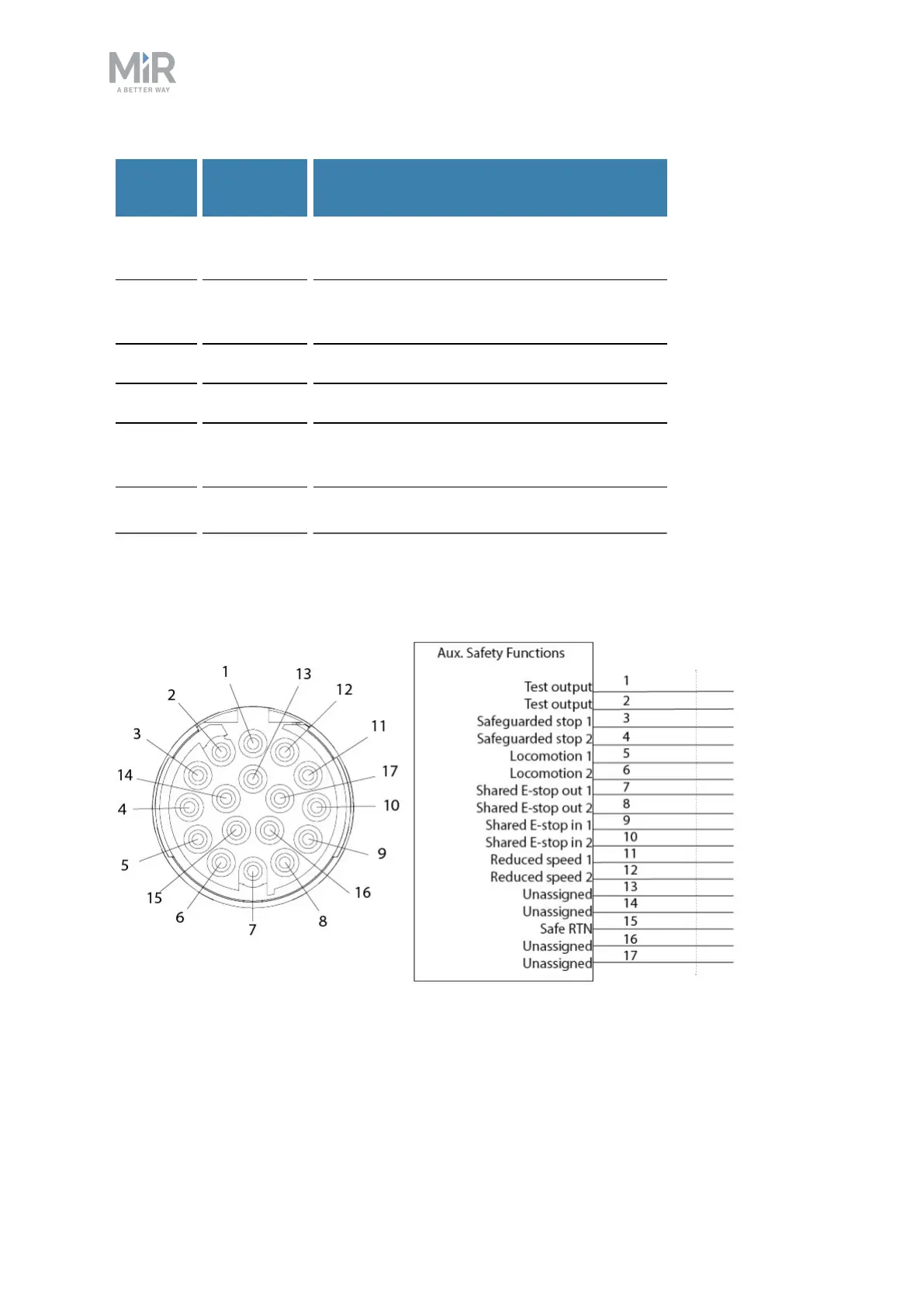
Auxiliary safety functions
An Auxiliary safety functions connection is provided in the top right-hand side compartment.
Figure 10.7. Pin numbers: female connector viewed from the front (left) and wiring diagram (right).
The Auxiliary safety functions interface is designed to support emergency stop and other
safety functions.