10. Interface specifications
MiR500 User guide (en) 09/2019 - v.1.3 ©Copyright 2018-2020: Mobile Industrial Robots A/S. 142
This enables the GPIO interface to work as input and output to top applications that can be
used in missions. The pallet lift feature uses a different kind of communication that is
specific to the pallet lift top module.
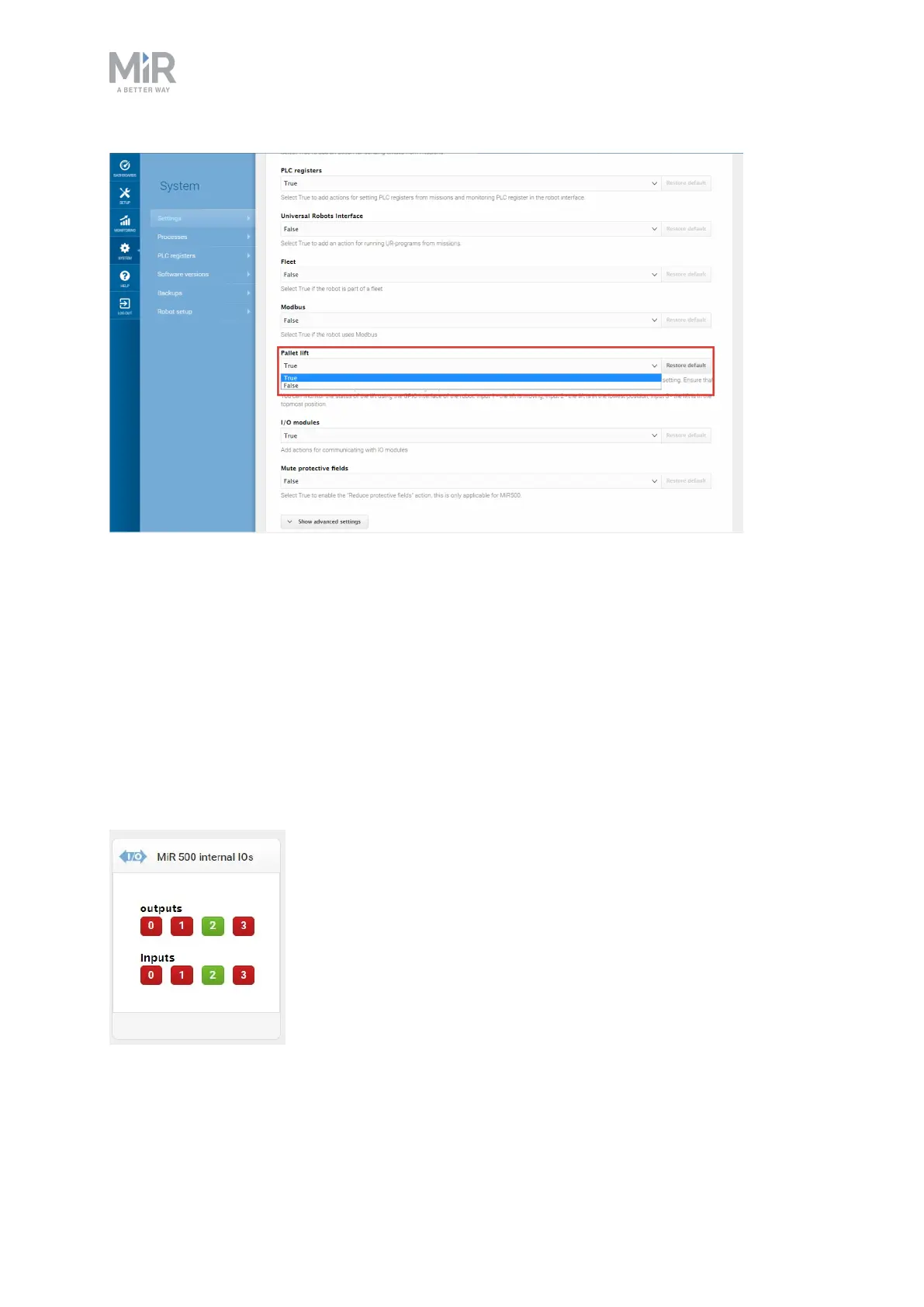
Outputs (O0, O1, O2, O3) can be toggled on and off by the robot in a Set I/Omodule
mission action or manually in Setup >I/O modules.
A top application can be connected to the output pins and monitor when they are high at
+24V. RTN is used as ground.
Inputs (I0, I1, I2, I3) can be used by the top application to send inputs to the robot. When
+24V is connected to the input pin, the robot registers the input as high.
Figure 10.4. Example of I2 registered as high by the robot.
 Loading...


