10. Interface specifications
MiR500 User guide (en) 09/2019 - v.1.3 ©Copyright 2018-2020: Mobile Industrial Robots A/S. 144
Ethernet
An Ethernet connection is in the top left-hand side compartment.
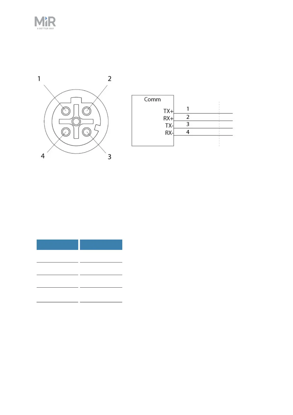
Figure 10.5. Ethernet connection. Pin numbers (left) and wiring diagram (right).
The communication interface is 10/100 Mbit Ethernet using a M12 connector. See
Connector list on page148.
Various protocols are supported, such as Modbus. For more information on how to use
Modbus, refer to the how-to guide How to use Modbus with MiRrobots found on the
Distributor site.
The following table contains the description of the pins of the Ethernet interface.
Pin number Signal name
1 TX+
2 RX+
3 TX-
4 RX-
 Loading...


