Chapter 6 Programming
6-71
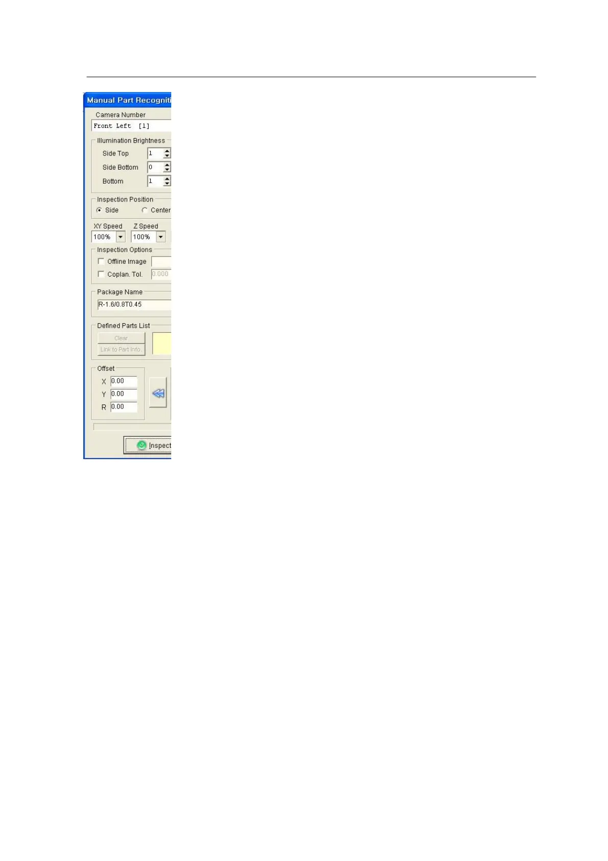
<Figure 6-67 가 Manual Part
Recognition window>
User can select Camera No, Head No, side/center, Don’t pickup,
etc. in the window.
1. Camera & Head No assignment table (Mx100/200)
Front Feeder Base (Parts are picked up by the front feeder.)
• Front Head 1 & 2 → Camera 1,5 are used. ( Mx100/200)
• Front Head 3 & 4 → Camera 2,6 are used. ( Mx100/200)
• Front Head 5 & 6 → Camera 3,7 are used. ( Mx200)
Rear Feeder Base (Parts are picked up by the rear feeder)
• Front Head 1 & 2 → Camera 5 is used. ( Mx100/200)
• Front Head 3 & 4 → Camera 6 is used. ( Mx100/200)
• Front Head 5 & 6 → Camera 7 is used. ( Mx200)
※ Some machines are not equipped with a rear camera (option).
In such a case, part inspection is carried out trough the front
camera.
• Precision Head → Camera 11 is used. ( Mx100/200)
Camera (CSP) 12,13 are used. ( Mx200P)
2. Side / Center
In Side inspection, two nozzles are inspected by one module camera. This is applied to
part dimension smaller than 18mm X 18mm. Center inspection is used for nozzle size
larger than 18mm X 18mm (Since camera recognition area is 18mm X 18mm, only those
parts smaller than 9mm X 9mm can be inspected when two nozzles are inspected by one
camera. Parts larger than 18mm X 18mm can be inspected only in center inspection.)
※ CSP, precision camera applies only the Center inspection.
3. Don’t pickup
Parts are inspected without pickup. ‘Don’t pickup’ is applied when part to be inspected is