4
MODBUS(R) STANDARD FUNCTIONS
4.20 Read/Write Multiple Registers (FC: 23)
4 - 60
1
OVERVIEW
2
SYSTEM
CONFIGURATION
3
SPECIFICATIONS
4
MODBUS(R) STANDARD
FUNCTIONS
5
FUNCTION
6
PRE-OPERATIONAL
PROCEDURES AND
SETTINGS
7
PARAMETER SETTING
8
UTILITY PACKAGE
(GX Configurator-MB)
4.20 Read/Write Multiple Registers (FC: 23)
Reads from or writes to multiple holding registers.
Writing is executed first and reading is then executed.
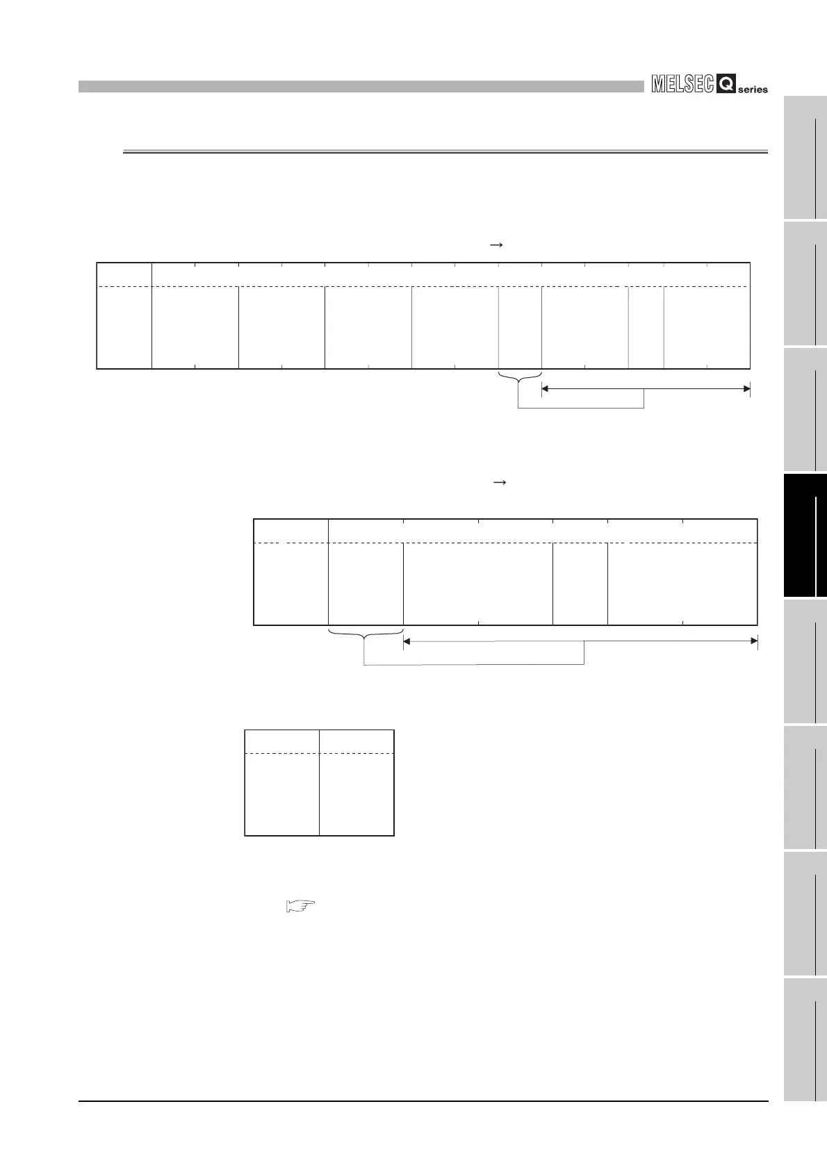
(1) Request message format (Master Slave)
* 1 The number of the specified write points must be matched with the number of bytes.
(2) Response message format (Slave Master)
(When completed normally)
(When completed with an error)
* 2 Exception and error codes are stored in the buffer memory in the case of error completion.
Refer to the following for storage location, confirmation methods, and detailed contents.
Section 11.4
Figure 4.98 Read/Write multiple registers (Request message)
Figure 4.99 Read/Write multiple registers (Normal response message)
Figure 4.100 Read/Write multiple registers (Exception message)
Data
(L) (L) (L)
. . .
(L) (L)(L)
Function
code
Function
code
(17
H)
Read head holding
register number
(0000
H to FFFFH)
Read points
n
(0001
H to 007DH)
Write head holding
register number
(0000
H to FFFFH)
Write points
m *1
(0001
H to 0079H)
Number of
bytes
m x 2 *1
(0000
H
to 00F2
H)
(Number of bytes m x 2)
Write
device data
1
Write
device data
m
(H)
(H)
(H)
(H)
(H) (H)
Data
(L)
. . .
Function code
Function
code
(17
H)
Number of
bytes
n x 2
Read
device data
1
Read
device data
n
(Number of bytes n x 2)
(L)
(H)
(H)
Data
Function code
Function code
(97
H)
Exception
code *
2
 Loading...


