7
PARAMETER SETTING
7.2 Automatic Communication Parameter
7.2.1 Automatic communication parameter details
7 - 4
1
OVERVIEW
2
SYSTEM
CONFIGURATION
3
SPECIFICATIONS
4
MODBUS(R) STANDARD
FUNCTIONS
5
FUNCTION
6
PRE-OPERATIONAL
PROCEDURES AND
SETTINGS
7
PARAMETER SETTING
8
UTILITY PACKAGE
(GX Configurator-MB)
7.2 Automatic Communication Parameter
Set the automatic communication parameters when using the automatic communication
function with the QJ71MB91 operated as a master.
( Section 5.2.1)
Up to 32 automatic communication parameters can be set for each channel.
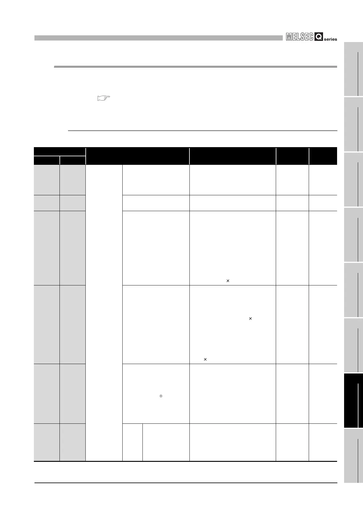
7.2.1 Automatic communication parameter details
(Continued on next page)
Table7.1 Automatic communication parameter list
Address
Parameter name Setting range Default Reference
CH1 CH2
0200
H
to
0201
H
(512 to
513)
0380
H
to
0381
H
(896 to
897)
Automatic
communication
parameter 1
Setting parameter existence
00000000
H
: Disabled
00000001
H
: Enabled
00000000
H
This
section (1)
0202
H
(514)
0382
H
(898)
Target station No.
0: Broadcast
1 to 247: Slave station No.
1
This
section (2)
0203
H
(515)
0383
H
(899)
Request interval timer value
0:
Upon reception of a reply message
from a slave, immediately issues the
next request message.
2 to 65535:
The time from when the QJ71MB91
sends a request message until it
sends the next request message (Set
time = set value 10 ms)
0
This
section (3)
0204
H
(516)
0384
H
(900)
Response monitoring timer
value/Broadcast delay value
Response monitoring timer value
(Target station No. is 1 to 247)
0 : 30 seconds
2 to 65535: Response monitoring
timer (Set time = set value 10 ms)
Broadcast delay value (Target station
No. is 0)
0: 400 ms
2 to 65535: Delay time (set time = set
value 10 ms)
0
This
section (4)
0205
H
(517)
0385
H
(901)
Type specification of the
target MODBUS device
0000
H
: Not specified
0100
H
: Read coils
0200
H
: Read discrete inputs
0400
H
: Read input registers
0500
H
: Read holding registers
0001
H
: Write coils
0005
H
: Write multiple registers
0505
H
: Read/Write multiple registers
0000
H
This
section (5)
0206
H
(518)
0386
H
(902)
Read
setting
Head buffer
memory address
0000
H
: None
1000
H
to 1FFF
H
:
CH1 read data storage area
2000
H
to 2FFF
H
:
CH2 read data storage area
0000
H
This
section (6)
 Loading...


