6
PRE-OPERATIONAL PROCEDURES AND SETTINGS
6.3 Part Names
6 - 4
1
OVERVIEW
2
SYSTEM
CONFIGURATION
3
SPECIFICATIONS
4
MODBUS(R) STANDARD
FUNCTIONS
5
FUNCTION
6
PRE-OPERATIONAL
PROCEDURES AND
SETTINGS
7
PARAMETER SETTING
8
UTILITY PACKAGE
(GX Configurator-MB)
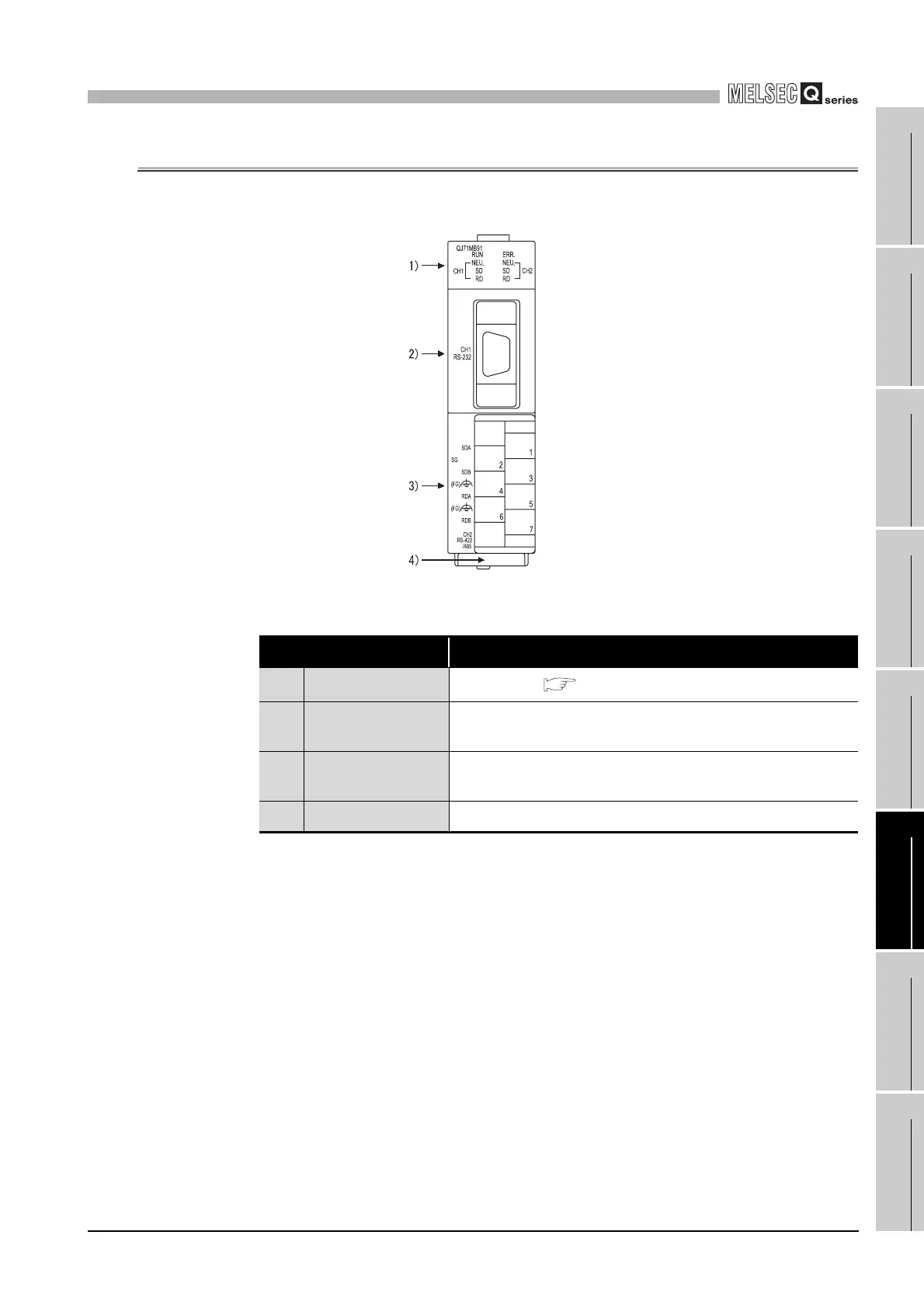
6.3 Part Names
This section provides the names of the QJ71MB91 parts.
Figure 6.2 QJ71MB91 external diagram
Table6.2 Part names and descriptions
Name Description
1) Indicator LED
Indicator LEDs ( This section (1))
2)
CH1 side RS-232
interface
RS-232 interface for serial communication with target devices
(D-Sub 9P)
3)
CH2 side RS-422/485
interface
RS-422/485 interface for serial communication with target devices
(Detachable terminal block)
4) Serial number plate Indicates the serial No. of the QJ71MB91.
 Loading...


