6
PRE-OPERATIONAL PROCEDURES AND SETTINGS
6.5 Connection to a Target Device
6.5.1 How to connect the RS-232 interface
6 - 12
1
OVERVIEW
2
SYSTEM
CONFIGURATION
3
SPECIFICATIONS
4
MODBUS(R) STANDARD
FUNCTIONS
5
FUNCTION
6
PRE-OPERATIONAL
PROCEDURES AND
SETTINGS
7
PARAMETER SETTING
8
UTILITY PACKAGE
(GX Configurator-MB)
6.5.1 How to connect the RS-232 interface
This section describes connection precautions and a connection example for using the
QJ71MB91 RS-232 interface.
(1) Connection precautions
(a) Connection cable's FG signal line and shield
Connect the connection cable's FG signal line and shield as follows:
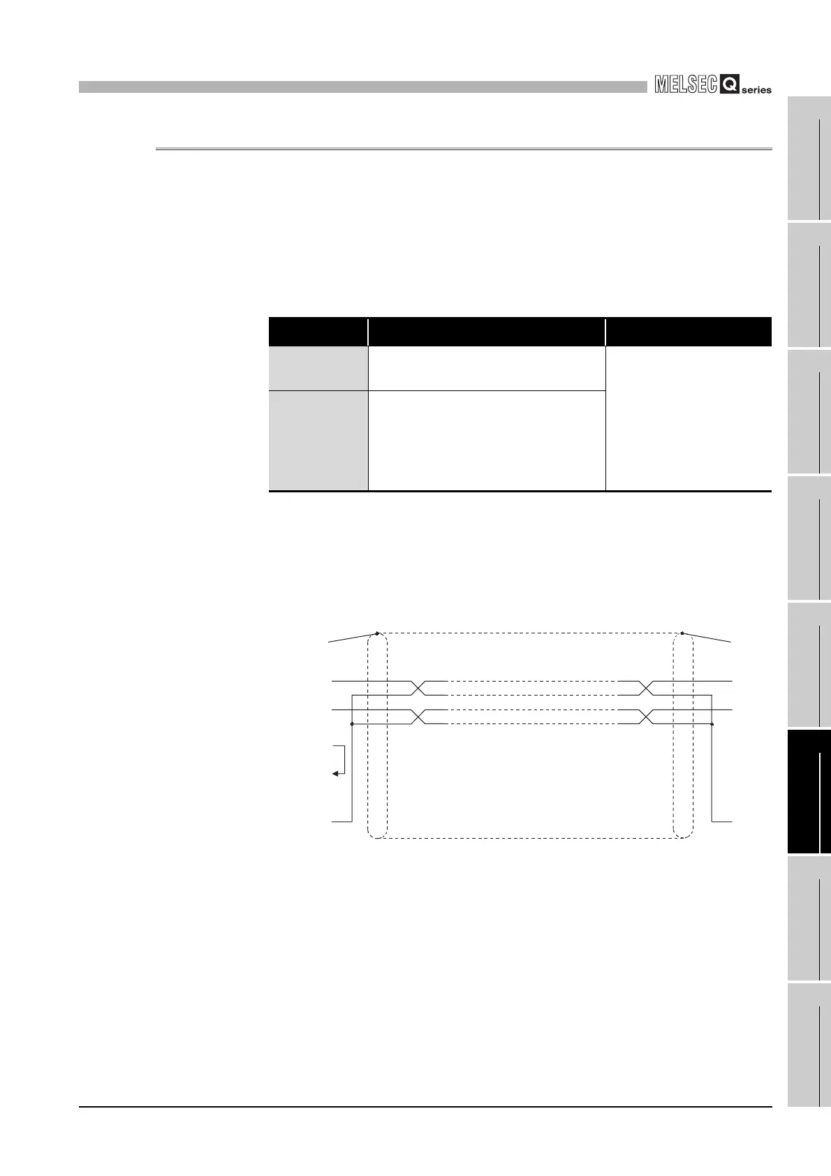
(b) Connection diagram
Connect the lines as shown below.
1) Connect the FG terminal on the target device and the QJ71MB91 side using
the shield of the connection cable.
2) Connect each signal line other than SG with the SG signal line in twisted pair.
Table6.5 Connection cable's FG signal line and shield
Item Connection on the QJ71MB91 side Remarks
Connection
cable's FG signal
Connect to the QJ71MB91 side connector
housing.
Do not short-circuit the FG and
SG signal lines of the
connection cable.
When the FG and SG signal
lines are connected inside the
target device, do not connect
the FG signal line to the
QJ71MB91 side.
Connecting
cable's shield
Connect to the target device's FG terminal or
the QJ71MB91 side connector housing.
Figure 6.9 RS-232 cable shield
FG
RD
SD
SG
RD
SD
SG
ShieldQJ71MB91 side Target device side
To connector
housing
Output for cable
disconnection
detection
Input for cable
disconnection
detection
 Loading...


