3
SPECIFICATIONS
3.5 Applications and Assignment of Buffer Memory
3.5.1 Buffer memory list
3 - 13
1
OVERVIEW
2
SYSTEM
CONFIGURATION
3
SPECIFICATIONS
4
MODBUS(R) STANDARD
FUNCTIONS
5
FUNCTION
6
PRE-OPERATIONAL
PROCEDURES AND
SETTINGS
7
PARAMETER SETTING
8
UTILITY PACKAGE
(GX Configurator-MB)
3.5 Applications and Assignment of Buffer Memory
3.5.1 Buffer memory list
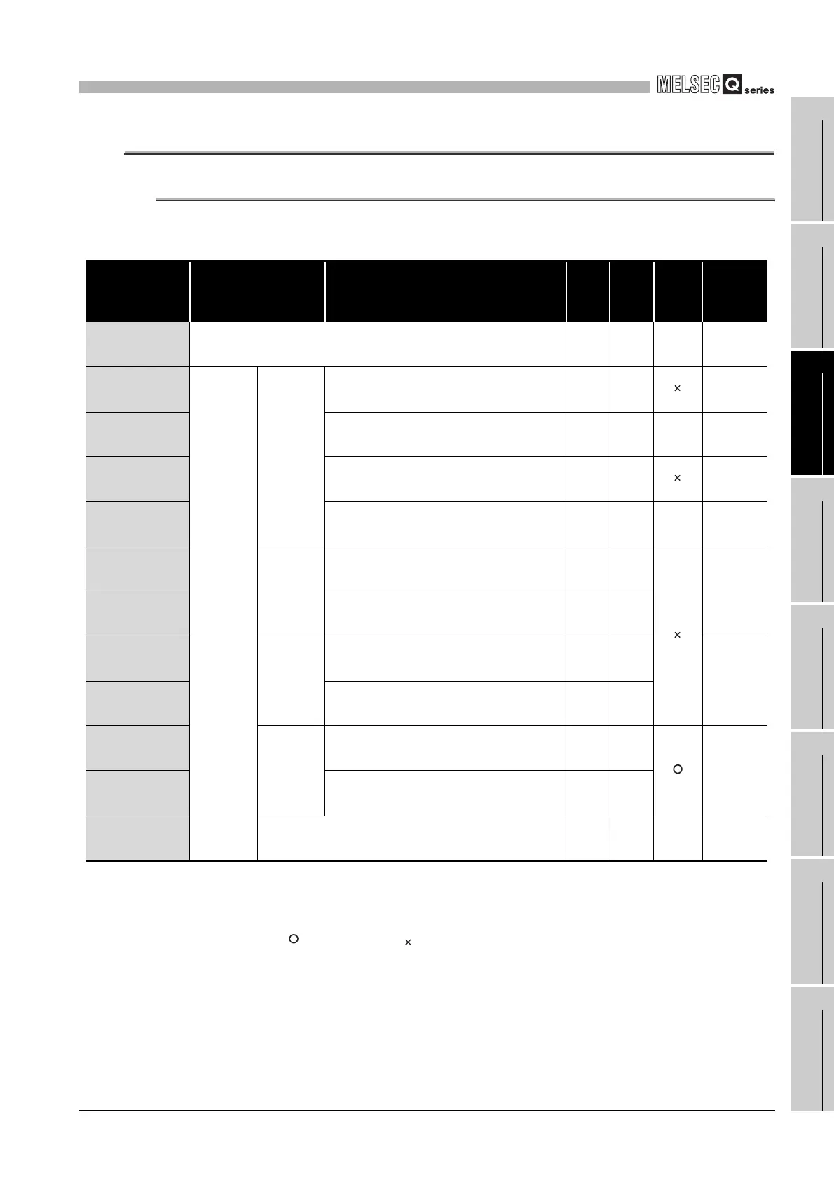
The buffer memory list is shown below.
* 1 Indicates whether the reading (Read)/writing (Write) from the sequence program is enabled or
disabled.
R: Readable W: Writable
* 2 Indicates whether setting on GX Configurator-MB is enabled or disabled.
: Setting enabled : Setting disabled
(Continued on next page)
Table3.4 Buffer memory list
Address Application Name
Initial
value
Read/
Write
(*1)
Initial
setting
(*2)
Reference
0000
H
to 0001
H
(0 to 1)
System area (use prohibited) - - - -
0002
H
(2)
Status
storage
area
Error code
CH1 side error response code storage area 0
H
R
Section
11.4.2
0003
H
(3)
System area (use prohibited) - - - -
0004
H
(4)
CH2 side error response code storage area 0
H
R
Section
11.4.2
0005
H
(5)
System area (use prohibited) - - - -
0006
H
(6)
Detailed
LED status
CH1 side detailed LED status storage area 0
H
R
Section
11.2
0007
H
(7)
CH2 side detailed LED status storage area 0
H
R
0008
H
(8)
Setting
area
Detailed
LED clear
request
CH1 side detailed LED clear request storage
area
0
H
R/W
Section
11.5
0009
H
(9)
CH2 side detailed LED clear request storage
area
0
H
R/W
000A
H
(10)
Setting
error status
read device
Device code F000
H
R/W
Section
7.3.4
000B
H
(11)
Head device number 0
H
R/W
000C
H
(12)
System area (use prohibited) - - - -
 Loading...


