3 - 14
3.5 Applications and Assignment of Buffer Memory
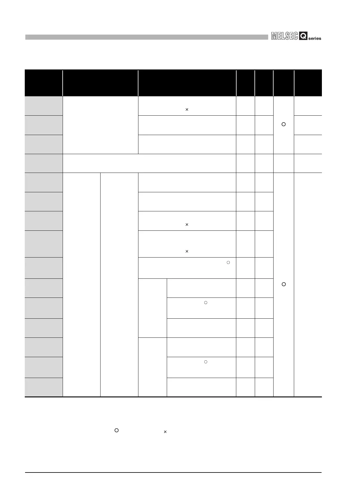
3.5.1 Buffer memory list
3
SPECIFICATIONS
* 1 Indicates whether the reading (Read)/writing (Write) from the sequence program is enabled or
disabled.
R: Readable W: Writable
* 2 Indicates whether setting on GX Configurator-MB is enabled or disabled.
: Setting enabled : Setting disabled
(Continued on next page)
Table3.4 Buffer memory list (Continued)
Address Application Name
Initial
value
Read/
Write
(*1)
Initial
setting
(*2)
Reference
000D
H
(13)
Setting area
CPU response monitoring timer value
Set time = set value 500ms
A
H
R/W
Section
7.3.6
000E
H
(14)
Access target (when mounted to
MELSECNET/H remote I/O station)
0
H
R/W
Section
7.3.5
000F
H
(15)
Allocated error status area 0
H
R/W
Section
7.3.4
0010
H
to 01FF
H
(16 to 511)
System area (use prohibited) - - - -
0200
H
to 0201
H
(512 to 513)
Automatic
communication
parameter
CH1 Automatic
communication
parameter 1
Setting parameter existence 0
H
R/W
Section 7.2
0202
H
(514)
Target station No. 1
H
R/W
0203
H
(515)
Request interval timer value
Set time = set value 10ms
0
H
R/W
0204
H
(516)
Response monitoring timer value/Broadcast
delay value
Set time = set value 10ms
0
H
R/W
0205
H
(517)
Type specification of the target MODBUS
device
0000
H
R/W
0206
H
(518)
Read
setting
Head buffer memory address 0000
H
R/W
0207
H
(519)
Target MODBUS device
head number
0
H
R/W
0208
H
(520)
Access points 0
H
R/W
0209
H
(521)
Write
setting
Head buffer memory address 0000
H
R/W
020A
H
(522)
Target MODBUS device
head number
0
H
R/W
020B
H
(523)
Access points 0
H
R/W
R
R
R
 Loading...


