6
PRE-OPERATIONAL PROCEDURES AND SETTINGS
6.4 Unit Tests
6.4.2 Self-loopback test
6 - 8
1
OVERVIEW
2
SYSTEM
CONFIGURATION
3
SPECIFICATIONS
4
MODBUS(R) STANDARD
FUNCTIONS
5
FUNCTION
6
PRE-OPERATIONAL
PROCEDURES AND
SETTINGS
7
PARAMETER SETTING
8
UTILITY PACKAGE
(GX Configurator-MB)
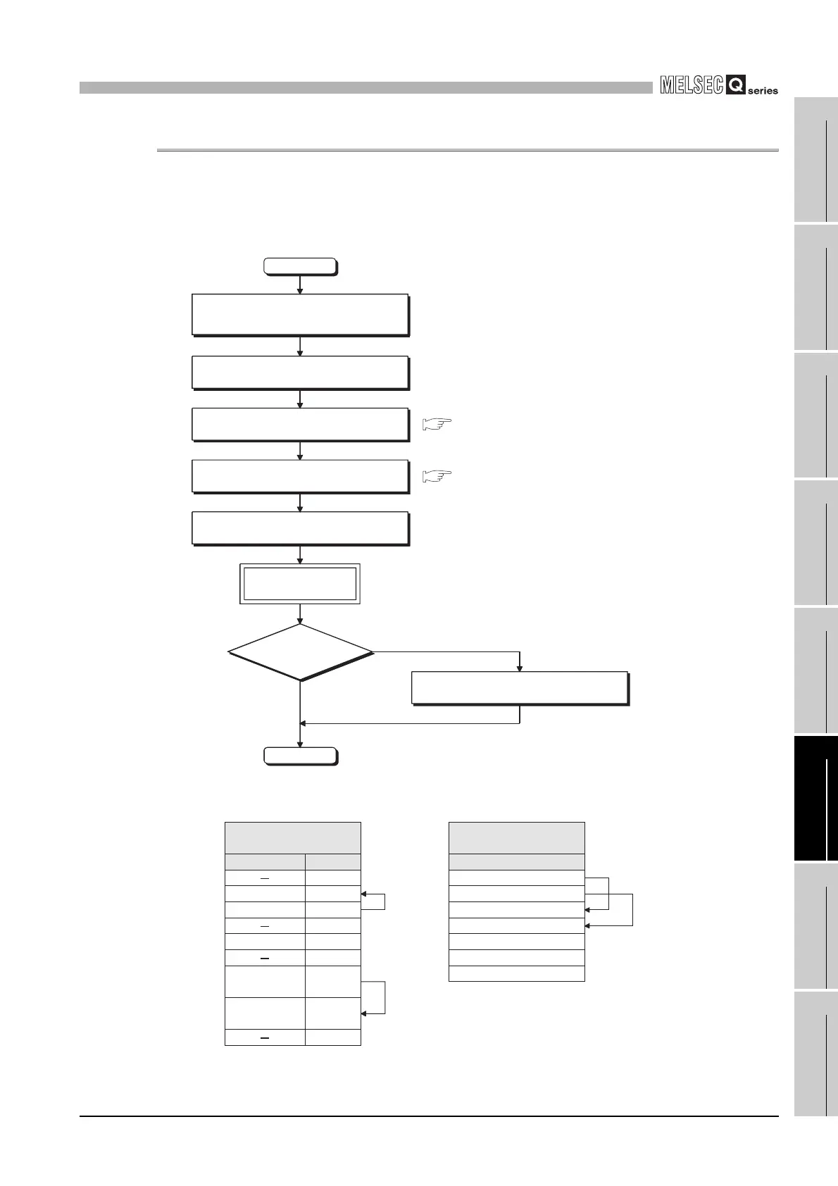
6.4.2 Self-loopback test
The self-loopback test checks the send/receive function of the QJ71MB91 and
communications with the programmable controller CPU.
(1) Self-loopback test procedure
* 1 This is the cable wiring for self-loopback test.
Figure 6.6 Self-loopback test procedure
Figure 6.7 Cable wirings for self-loopback test
Start
STOP the programmable controller CPU.
Disconnect the communication cable connected to
the target device.
Connect a cable for self-loopback test.*1
Make the communication
speed/transmission settings. (Switch 2, 4)
Set it to the self-loopback test mode.
(Switch 1, 3 = 000D
H, 000EH combination)
Reset the programmable controller CPU.
Loopback test execution
(approx. 1 second per cycle)
Normal/Error
ERR.LED ON: Error completion
ERR.LED OFF:
Normal operation
End
Monitor the buffer memory and check the
error.
Section 6.6
Section 6.6
RD
SD
1
2
3
4
5
6
7
8
9
SDB
RDA
RDB
SG
SDA
FG
FG
QJ71MB91
CH1(RS
-
232)
Signal name
Pin No.
SG
Output for cable
disconnection
detection
Input for cable
disconnection
detection
QJ71MB91
CH2 (RS-422/485)
Signal name
 Loading...


