4
MODBUS(R) STANDARD FUNCTIONS
4.11 Diagnostics (FC: 08)
4.11.3 Return diagnostic register (sub-function code: 02)
4 - 28
1
OVERVIEW
2
SYSTEM
CONFIGURATION
3
SPECIFICATIONS
4
MODBUS(R) STANDARD
FUNCTIONS
5
FUNCTION
6
PRE-OPERATIONAL
PROCEDURES AND
SETTINGS
7
PARAMETER SETTING
8
UTILITY PACKAGE
(GX Configurator-MB)
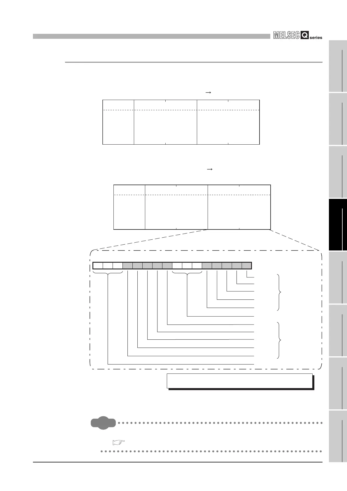
4.11.3 Return diagnostic register (sub-function code: 02)
Reads out the detailed LED status of the QJ71MB91 to the master.
(1) Request message format (Master Slave)
(2) Response message format (Slave Master)
(When completed normally)
Remark
Refer to the following for each items of the detailed LED status.
Section 11.2
Figure 4.32 Return diagnostic register (Request message)
Figure 4.33 Return diagnostic register (Normal response message)
(L)
Data
(L)
Function code
Function
code
(08
H)
Sub-function code
Sub-function code
(0002
H)
(0000
H)
(H) (H)
(L)
Data
(L)
b0b1b2b3b4b5b6b7b8b9b10b11b12b13b14b15
Unused (Fixed to 0)
0 0 0 1/0 1/0 1/0 1/0 1/0 0 0 0 1/0 1/0 1/0 1/0 1/0
Function code
Function
code
(08
H)
Sub-function code
Sub-function code
(0002
H)
Diagnostic register
value
CH1 C/N
CH1 P/S
CH1 PRO.
CH1 SIO
CH1 ERR.
CH1 side Detailed
LED status
(0: OFF, 1: ON)
CH2 C/N
CH2 P/S
CH2 PRO.
CH2 SIO
CH2 ERR.
CH2 side Detailed
LED status
(0: OFF, 1: ON)
Unused (Fixed to 0)
The QJ71MB91 stores the lower 8 bits of the buffer memory's
Detailed LED status as a diagnostic register. (address: 0006
H/0007H)
(H)
(H)
 Loading...


