3
SPECIFICATIONS
3.2 RS-232 Interface Specification
3.2.1 RS-232 connector specification
3 - 3
1
OVERVIEW
2
SYSTEM
CONFIGURATION
3
SPECIFICATIONS
4
MODBUS(R) STANDARD
FUNCTIONS
5
FUNCTION
6
PRE-OPERATIONAL
PROCEDURES AND
SETTINGS
7
PARAMETER SETTING
8
UTILITY PACKAGE
(GX Configurator-MB)
3.2 RS-232 Interface Specification
This section explains RS-232 interface specifications.
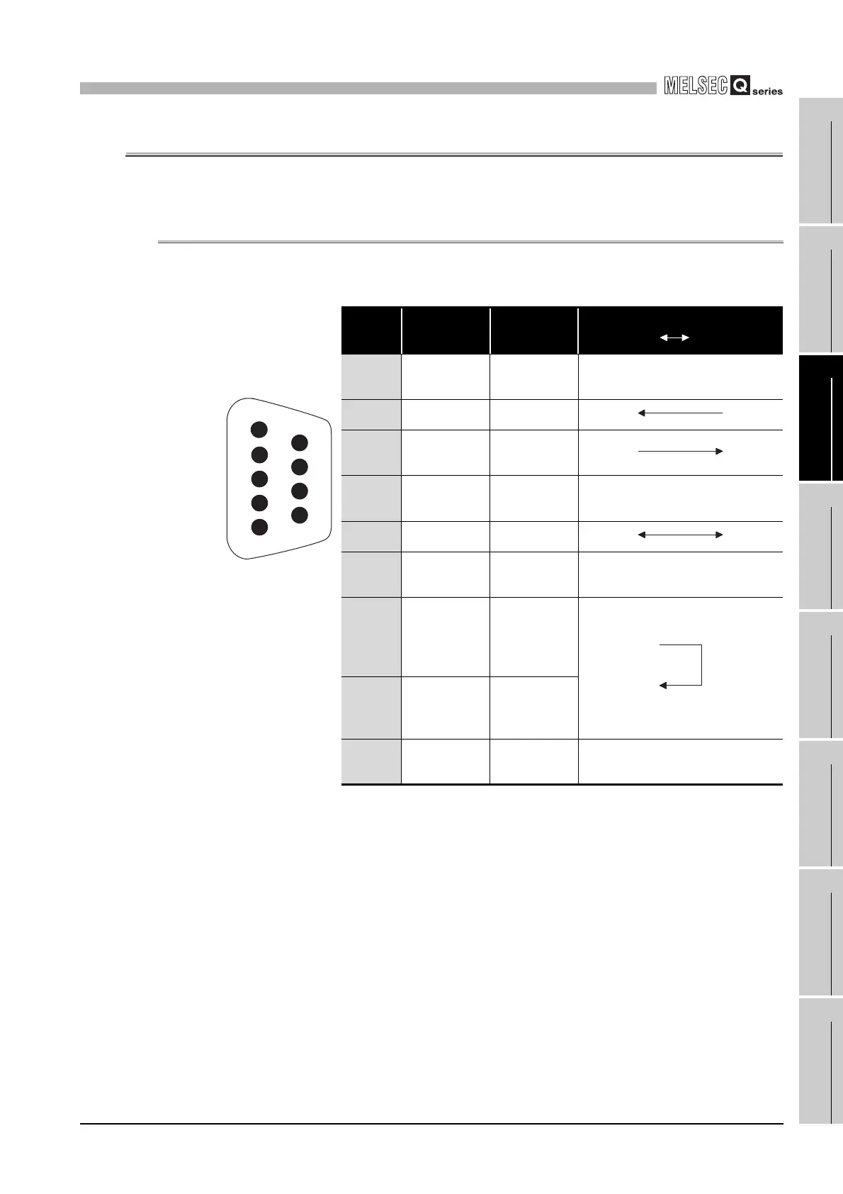
3.2.1 RS-232 connector specification
This section provides the specifications of RS-232 connector that is connected to a target
device.
* 1 Connect Pin 8 to Pin 7.
Without connecting Pin 7 and 8, Pin 8 turns off and the CS signal may turn off (error code: 7403
H).
(1) Descriptions of control signals
The following explains control signals. (The pin number of the connector is indicated
within the brackets.)
(a) RD signal (2)
Signal for receiving data.
(b) SD signal (3)
Signal for sending data.
Pin
number
Signal code Signal name
Signal direction
QJ71MB91 Target device
1
(Use
prohibited)
(Use
prohibited)
-
2 RD (RXD) Reception data
3SD (TXD)
Transmission
data
4
(Use
prohibited)
(Use
prohibited)
-
5 SG (GND) Signal ground
6
(Use
prohibited)
(Use
prohibited)
-
7
*1
-
Output for
cable
disconnection
detection
8
*1
-
Input for cable
disconnection
detection
9
(Use
prohibited)
(Use
prohibited)
-
Figure 3.1 RS-232 connector specification
1
2
3
4
5
6
7
8
9
 Loading...


