9
PROGRAMMING
9.2 Program Example for Normal System Configuration
9.2.2 MODBUS(R) device assignment parameters
9 - 14
9
PROGRAMMING
10
DEDICATED
INSTRUCTIONS
11
TROUBLESHOOTINGAPPENDICESINDEX
9.2.2 MODBUS(R) device assignment parameters
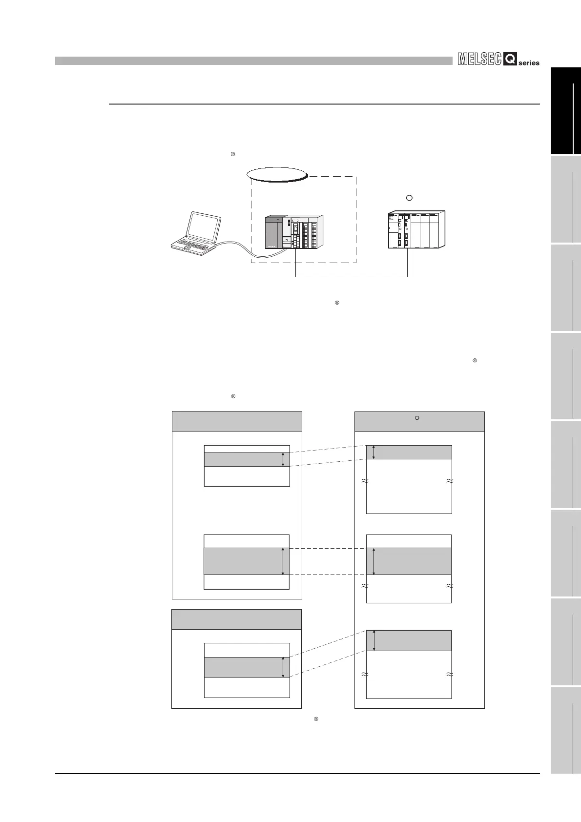
(1) System configuration
The following system configuration is used to explain a program example for setting
the MODBUS device assignment parameters to the QJ71MB91.
* 1 The QJ71MB91 is to be mounted in slot 0 of the base unit with the head I/O number set to “00H”.
(2) Communications
In the program example shown in this section, the following MODBUS device
assignment parameters are set for the setting target , QJ71MB91.
(a) MODBUS device assignment parameter assignment diagram
Figure 9.14 System configuration example for the MODBUS device assignment parameter setting
Figure 9.15 MODBUS device assignment diagram
RS-422/485
GX Developer
R
Setting target
QJ71MB91
*1
(Slave function)
(Station No.1)
MODBUS master device
CH2
R
Output (Y)
Coil
000001Y0
Y100
Y2FF
Y1FFF
065536
300001
303500
D3500
D8999
D12287
365536
308999
400001
401024
465536
Programmable controller
CPU device memory
000512
512 points
Data register (D)
5500 points
D0
QJ71MB91 buffer memory
User free area
5000H
5500H
58FFH
5FFFH
1024 points
MODBUS device
512 points
5500 points
Holding register
Input register
1024 points
 Loading...


