3
SPECIFICATIONS
3.5 Applications and Assignment of Buffer Memory
3.5.1 Buffer memory list
3 - 15
1
OVERVIEW
2
SYSTEM
CONFIGURATION
3
SPECIFICATIONS
4
MODBUS(R) STANDARD
FUNCTIONS
5
FUNCTION
6
PRE-OPERATIONAL
PROCEDURES AND
SETTINGS
7
PARAMETER SETTING
8
UTILITY PACKAGE
(GX Configurator-MB)
* 1 Indicates whether the reading (Read)/writing (Write) from the sequence program is enabled or
disabled.
R: Readable W: Writable
* 2 Indicates whether setting on GX Configurator-MB is enabled or disabled.
: Setting enabled : Setting disabled
(Continued on next page)
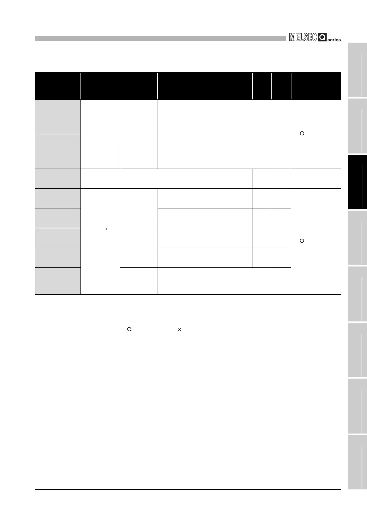
Table3.4 Buffer memory list (Continued)
Address Application Name
Initial
value
Read/
Write
(*1)
Initial
setting
(*2)
Reference
020C
H
to 037F
H
(524 to 895)
Automatic
communication
parameter
CH1 Automatic
communication
parameter 2 to
32
(Same as CH1 Automatic communication parameter 1)
Section
7.2
0380
H
to 04FF
H
(896 to 1279)
CH2 Automatic
communication
parameter 1 to
32
(Same as CH1 Automatic communication parameter 1)
0500
H
to 08FF
H
(1280 to 2303)
System area (use prohibited) - - - -
0900
H
(2304)
MODBUS
device
assignment
parameter
Coil
assignment 1
Device code 0
H
R/W
Section
7.3.1
0901
H
(2305)
Head device number 0
H
R/W
0902
H
(2306)
Head coil number 0
H
R/W
0903
H
(2307)
Assignment points 0
H
R/W
0904
H
to 093F
H
(2308 to 2367)
Coil
assignment 2
to 16
(Same as in Coil assignment 1)
 Loading...


