6
PRE-OPERATIONAL PROCEDURES AND SETTINGS
6.5 Connection to a Target Device
6.5.2 How to connect the RS-422/485 interface
6 - 16
1
OVERVIEW
2
SYSTEM
CONFIGURATION
3
SPECIFICATIONS
4
MODBUS(R) STANDARD
FUNCTIONS
5
FUNCTION
6
PRE-OPERATIONAL
PROCEDURES AND
SETTINGS
7
PARAMETER SETTING
8
UTILITY PACKAGE
(GX Configurator-MB)
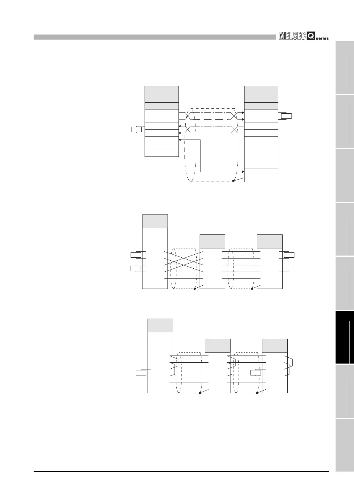
(2) Connection examples
(a) Connection for 1:1 communication
(b) Connection for 1:n communication when host is master
1) For 4-wire communications
2) For 2-wire communications
Figure 6.13 Connection for 1:1 communication
Figure 6.14 Connection (for 1:n communication, 4 wire) when host is master
Figure 6.15 Connection (for 1:n communication, 2 wires) when host is master
Terminating
resistor
R
RDA
SG
FG
SDA
Signal name
RDA
SG
FG
Target device
Slave or
Master
SDA
Terminating
resistor
R
QJ71MB91 (CH2)
Master or Slave
Signal name
SDB
RDB
RDB
SDB
Terminating
resistor
R
RDA
SG
FG
SDA
Terminating
resistor
R
Terminating
resistor
R
RDA
SG
FG
QJ71MB91
SDA
Terminating
resistor
R
SDB
RDB
RDB
SDB
RDA
SG
FG
SDA
RDB
SDB
Third party
slave
Third party
slave
RDA
SG
FG
SDA
R R
SDB
RDB
RDA
SG
FG
SDA
SDB
RDB
RDA
SG
FG
SDA
SDB
RDB
QJ71MB91
Terminating
resistor
Third party
slave
Third party
slave
 Loading...


