6
PRE-OPERATIONAL PROCEDURES AND SETTINGS
6.5 Connection to a Target Device
6.5.2 How to connect the RS-422/485 interface
6 - 18
1
OVERVIEW
2
SYSTEM
CONFIGURATION
3
SPECIFICATIONS
4
MODBUS(R) STANDARD
FUNCTIONS
5
FUNCTION
6
PRE-OPERATIONAL
PROCEDURES AND
SETTINGS
7
PARAMETER SETTING
8
UTILITY PACKAGE
(GX Configurator-MB)
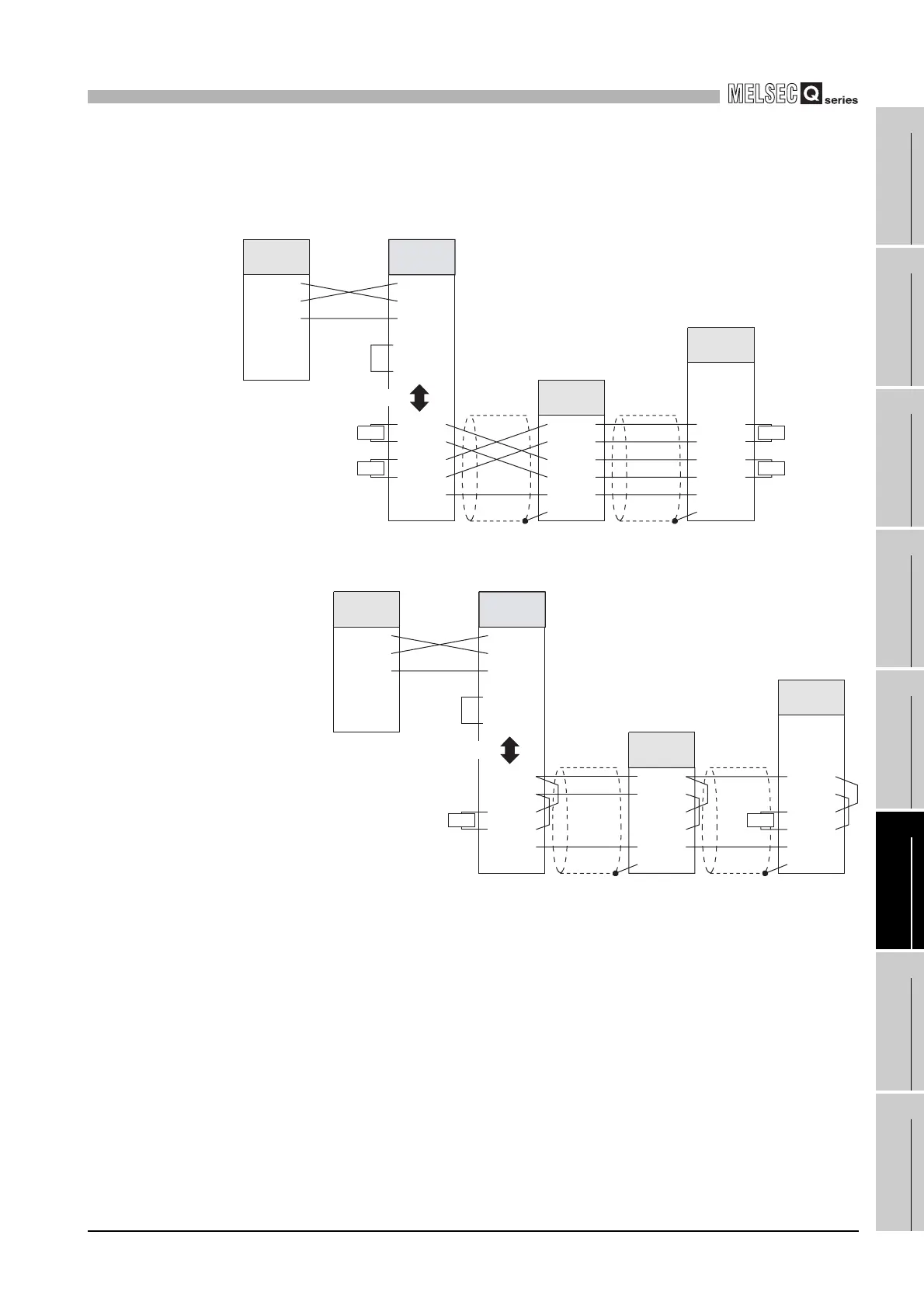
2) When performing 1:n communication with a third party master station (RS-232
interface)
(Link operation setting)
< For 4-wire communications >
< For 2-wire communications >
Figure 6.18 Connection (for link operation setting, 1:n communication, 4 wires) when host is slave
Figure 6.19 Connection (for link operation setting, 1:n communication, 2 wires) when host is slave
R R
RR
RDA
SG
FG
SDA
SDB
RDB
RDA
SG
FG
SDA
SDB
RDB
RDA
SG
FG
SDA
SDB
RDB
QJ71MB91
SG
SD
RD
SG
SD
RD
Terminating
resistor
Terminating
resistor
Terminating
resistor
QJ71MB91
Terminating
resistor
RS-232
Link operation
setting
Output for cable
disconnection
detection
Input for cable
disconnection
detection
Third party
slave
Third party
master
SG
SD
RD
RDA
SG
FG
SDA
SDB
RDB
QJ71MB91
QJ71MB91
R
RS-232
RDA
SG
FG
SDA
SDB
RDB
RDA
SG
FG
SDA
SDB
RDB
R
SG
SD
RD
Terminating
resistor
QJ71MB91
Output for cable
disconnection
detection
Input for cable
disconnection
detection
Link operation
setting
Third party
slave
Third party
master
 Loading...


