7
PARAMETER SETTING
7.2 Automatic Communication Parameter
7.2.1 Automatic communication parameter details
7 - 10
1
OVERVIEW
2
SYSTEM
CONFIGURATION
3
SPECIFICATIONS
4
MODBUS(R) STANDARD
FUNCTIONS
5
FUNCTION
6
PRE-OPERATIONAL
PROCEDURES AND
SETTINGS
7
PARAMETER SETTING
8
UTILITY PACKAGE
(GX Configurator-MB)
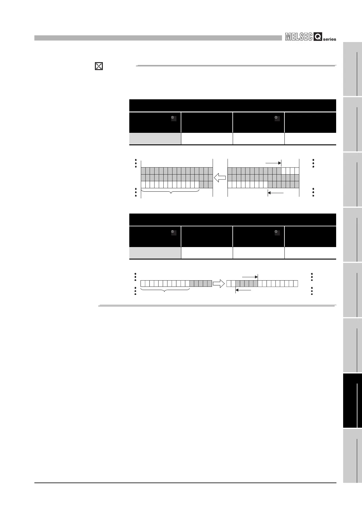
POINT
In the access to a bit device (coil/input) of a slave, the fraction bits are handled as
described below.
• Bit device read
• Bit device write
Automatic communication parameter: Read setting
Target MODBUS
device type setting
Head buffer memory
address
Target MODBUS
device head number
Access points
0200H (input) 1000H (4096) 16628 35
Automatic communication parameter: Write setting
Target MODBUS
Device type setting
Head buffer
Memory address
Target MODBUS
device head number
Access points
0001H (coil) 3000H (12288) 1305 5
to
Remaining area is masked with 0
Read
to
116629
116663
<QJ71MB91 buffer memory>
<Target slave device area>
b15 b15
116640 to 116625
116656 to 116641
116672 to 116657
b0
b0
1000
H
1001
H
1002
H
Write
toto
001306
001310
<QJ71MB91 buffer memory>
b15
b15
Remaining
area is ignored
001312 to 001297
3000
H
<Target slave device area>
b0 b0
 Loading...


