7
PARAMETER SETTING
7.3 MODBUS(R) Device Assignment Parameter
7 - 12
1
OVERVIEW
2
SYSTEM
CONFIGURATION
3
SPECIFICATIONS
4
MODBUS(R) STANDARD
FUNCTIONS
5
FUNCTION
6
PRE-OPERATIONAL
PROCEDURES AND
SETTINGS
7
PARAMETER SETTING
8
UTILITY PACKAGE
(GX Configurator-MB)
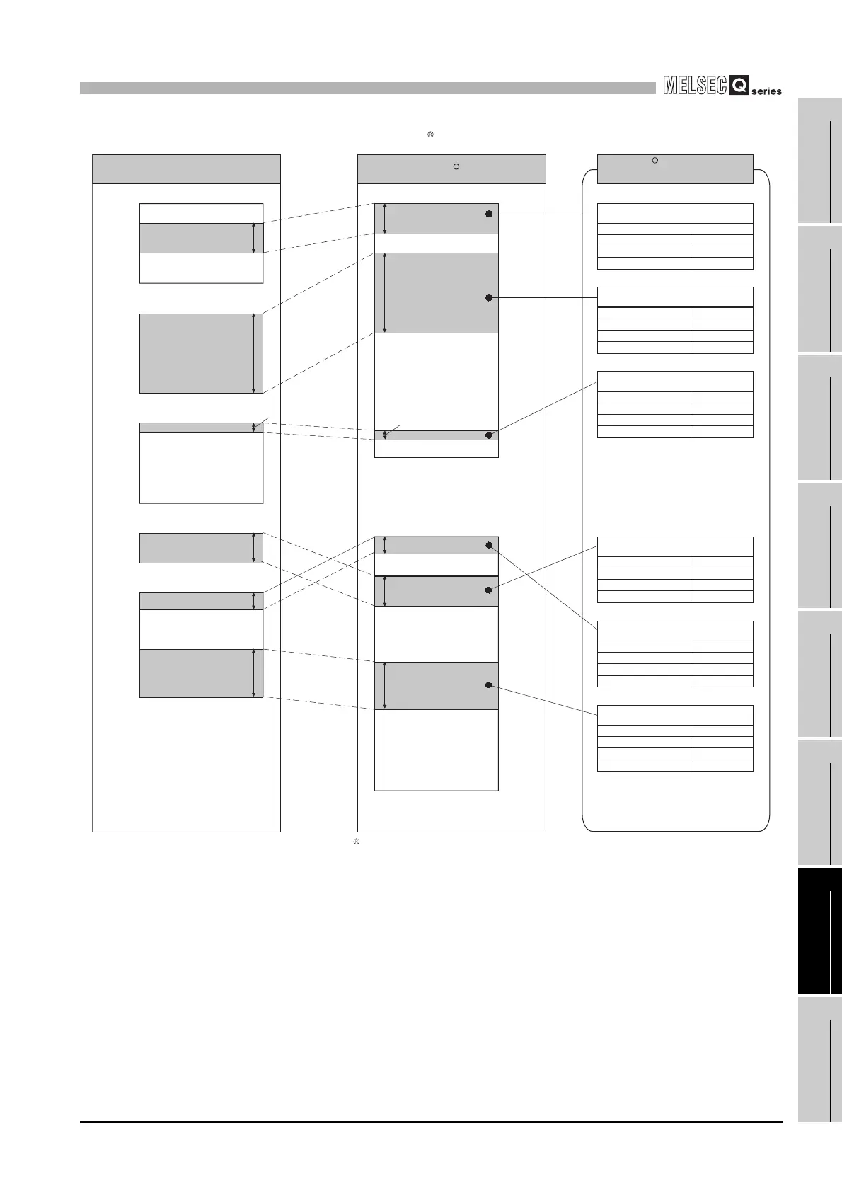
[Schematic diagram of MODBUS device assignment parameter setting]
Figure 7.7 MODBUS device assignment parameter setting diagram
R
Coil
012191
065536
400001
465536
3500
8192
2048
1000
6288
436287
M8191
8192
Y1FFF
5
L4
L8191
2048
SD2047
1000
D999
D6000
6288
D12287
1201
0
3500
0
3999
8192
0
64999
5
1999
2048
0
1000
6000
29999
6288
5
Programmable controller
CPU device
Internal relay (M)
Output (Y)
Latch relay (L)
Special register (SD)
Data register (D)
R
MODBUS device
Holding register
MODBUS device assignment
parameter setting example
Coil assignment 1
Device code
Head device number
Head coil number
Assignment points
M(0090
H)
Coil assignment 2
Device code
Head device number
Head coil number
Assignment points
Y(009D
H)
Coil assignment 3
Device code
Head device number
Head coil number
L(0092
H)
Holding register assignment 1
Device code
Head device number
Head holding register number
Assignment points
SD(00A9
H)
Holding register assignment 2
Device code
Assignment points
D(00A8
H)
Holding register assignment 3
Device code
Assignment points
D(00A8
H)
M4700
M1201
M0
3500
Y0
L0
SD0
D0
000001
003500
004000
065000
065004
401000
404047
402000
430000
Assignment points
0
Head device number
0
Head holding register number
Head device number
Head holding register number
 Loading...


