7
PARAMETER SETTING
7.3 MODBUS(R) Device Assignment Parameter
7.3.1 MODBUS(R) device assignment to the programmable controller CPU device memory
7 - 16
1
OVERVIEW
2
SYSTEM
CONFIGURATION
3
SPECIFICATIONS
4
MODBUS(R) STANDARD
FUNCTIONS
5
FUNCTION
6
PRE-OPERATIONAL
PROCEDURES AND
SETTINGS
7
PARAMETER SETTING
8
UTILITY PACKAGE
(GX Configurator-MB)
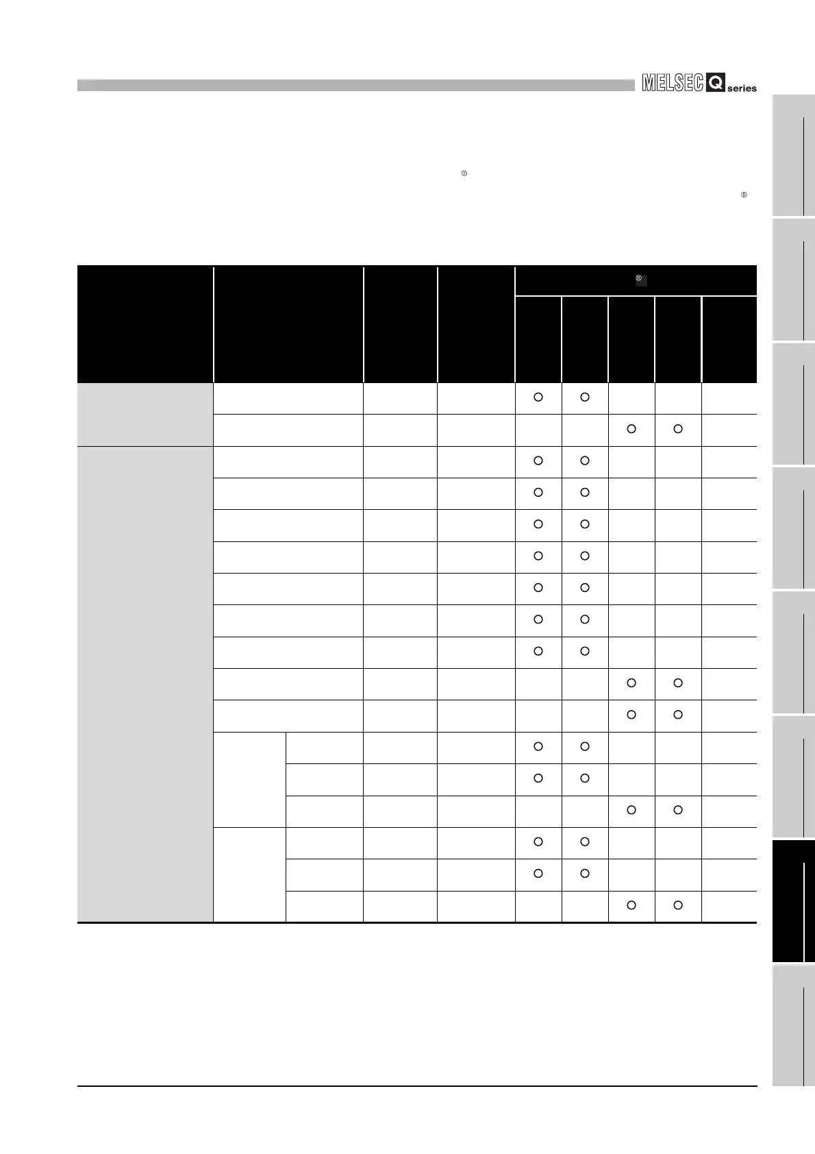
1) Device code
Set programmable controller CPU devices and QJ71MB91 buffer memory to
be assigned to the MODBUS devices.
The device codes have different setting abilities depending on the MODBUS
devices.
Refer to the following table for the device code setting availabilities.
(Continued on next page)
Table7.7 Device code list
Classification Device name
Device
symbol
Device code
*5
MODBUS device
Coil Input
Input
Register
Holding
Register
Extension
File
Register
Internal system device
Special relay
SM
*3
0091
H
Special register
SD
*3
00A9
H
Internal user device
Input
X
*3
009C
H
Output
Y
*3
009D
H
Internal relay
M
*3
0090
H
Latch relay L 0092
H
Annunciator F 0093
H
Edge relay V 0094
H
Link relay
B
*3*4
00A0
H
Data register
D
*3*6
00A8
H
Link register
W
*3*4*6
00B4
H
Timer
Coil TC 00C0
H
Contact TS 00C1
H
Current value TN 00C2
H
Retentive
timer
Coil SC 00C6
H
Contact SS 00C7
H
Current value SN 00C8
H
 Loading...


