7 - 27
7.3 MODBUS(R) Device Assignment Parameter
7.3.4 Specifying the error status read device
7
PARAMETER SETTING
(a) Device code
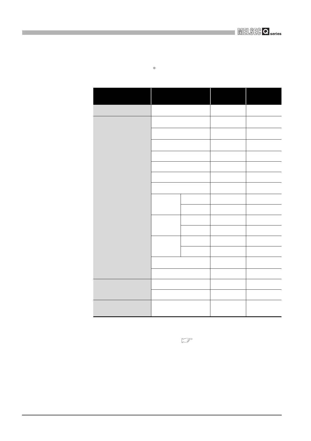
Set programmable controller CPU devices and QJ71MB91 buffer memory to be
assigned to the MODBUS devices.
The device codes usable for the error status read devices are indicated below.
* 1 When the access target is the MELSECNET/H remote I/O station to which the QJ71MB91 is
mounted, only this device is supported.
When a device other than the above is assigned, and if Read Exception Status (FC: 07) is sent
from the master, an error will be generated.( Section 7.3.5)
* 2 Equivalent to LB of the MELSECNET/H remote I/O stations.
* 3 When setting with GX Configurator-MB, input the head device.
Table7.11 Device codes usable for error status read devices
Classification Device name Device symbol
Device code
*3
Internal system device Special relay
SM
*1
0091
H
Internal user device
Input
X
*1
009C
H
Output
Y
*1
009D
H
Internal relay
M
*1
0090
H
Latch relay L 0092
H
Annunciator F 0093
H
Edge relay V 0094
H
Link relay
B
*1*2
00A0
H
Timer
Coil TC 00C0
H
Contact TS 00C1
H
Retentive
timer
Coil SC 00C6
H
Contact SS 00C7
H
Counter
Coil CC 00C3
H
Contact CS 00C4
H
Special link relay
SB
*1
00A1
H
Step relay S 0098
H
Direct device
Direct input DX 00A2
H
Direct output DY 00A3
H
QJ71MB91 buffer memory
Error status read buffer
memory (address: 000F
H)
- F000
H
 Loading...


