8
UTILITY PACKAGE (GX Configurator-MB)
8.6 Monitor/Test
8.6.5 Communication status
8 - 37
1
OVERVIEW
2
SYSTEM
CONFIGURATION
3
SPECIFICATIONS
4
MODBUS(R) STANDARD
FUNCTIONS
5
FUNCTION
6
PRE-OPERATIONAL
PROCEDURES AND
SETTINGS
7
PARAMETER SETTING
8
UTILITY PACKAGE
(GX Configurator-MB)
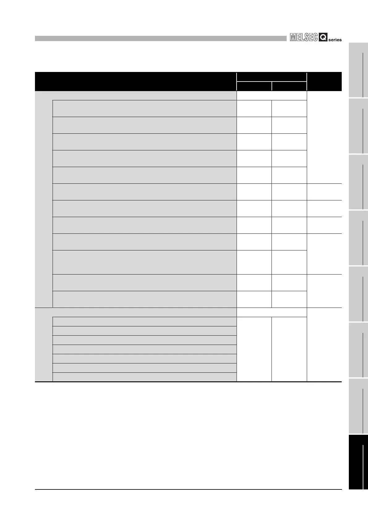
Table8.16 Setting items on the Communication status screen (Continued)
Monitor item
Buffer memory address
Reference
CH1 CH2
Diagnostic data for Slave -
Section 11.3
Slave message count
0F06
H
(3846)
0F46
H
(3910)
Slave no-response count
0F07
H
(3847)
0F47
H
(3911)
Slave NAK count
0F08
H
(3848)
0F48
H
(3912)
Slave busy count
0F09
H
(3849)
0F49
H
(3913)
Exception error count
0F0A
H
(3850)
0F4A
H
(3914)
Communications event count
0F0B
H
(3851)
0F4B
H
(3915)
Section 4.12
2nd byte of end code
0F0C
H
(3852)
0F4C
H
(3916)
Section 4.11.4
Communications mode
0F0D
H
(3853)
0F4D
H
(3917)
Section 4.11.5
Communications event log count
0F1F
H
(3871)
0F5F
H
(3935)
Section 4.13
Communications event log 1 to 64
0F20
H to
0F3F
H(3872
to 3903)
0F60
H to
0F7F
H(3936
to 3967)
Error response code presence
0006
H
(6)
0007
H
(7)
Section 11.4.2
Error response code storage area
0002
H
(2)
0004
H
(4)
LED status -
Section 11.2
C/N
0006
H
(6)
0007
H
(7)
P/S
PRO.
SIO
NEU.
ACK.
NAK
 Loading...


