2 - 7
2.2 Network Configuration
2
SYSTEM CONFIGURATION
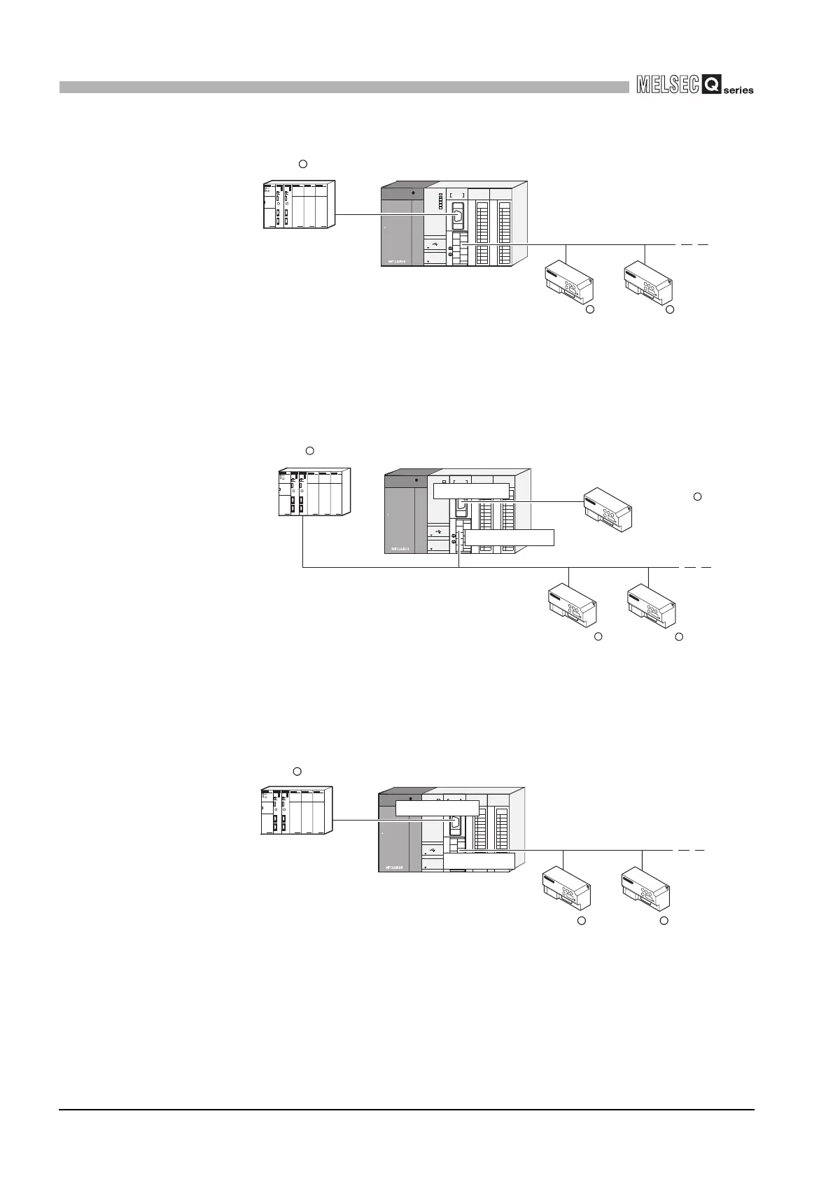
(e) Connecting to a master station (1:n) with the link operation function
(3) Connecting master and slave stations separately through each interface
(a) Using the RS-232 interface as the master station and the RS-422/485 interface as
the slave station
(b) Using the RS-232 interface as the slave station and the RS-422/485 interface as
the master station
Figure 2.9 Connecting to a master station (1:n) with the link operation function
Figure 2.10 Using the RS-232 interface as the master station and the RS-422/485
interface as the slave station
Figure 2.11 Using the RS-232 interface as the slave station and the RS-422/485 interface
as the master station
4
2
5
3
1
6
7
(FG)
(FG)
RS-232
/485
RS-422
CH2
RDB
RDA
SDB
SG
SDA
CH1
QJ71MB91
RUN
RD
NEU.
SD
NEU.
RD
SD
CH1
CH2
ERR.
R
R
RS-485
RS-232
MODBUS master device
QJ71MB91 (Slave function)
MODBUS
slave device
R
MODBUS
slave device
4
2
5
3
1
6
7
(FG)
(FG)
RS-232
/485
RS-422
CH2
RDB
RDA
SDB
SG
SDA
CH1
QJ71MB91
RUN
RD
NEU.
SD
NEU.
RD
SD
CH1
CH2
ERR.
QJ71MB91
R
RS-485
RS-232
MODBUS
R
MODBUS master device
(Master function)
(Slave function)
slave device
MODBUS
R
slave device
MODBUS
R
slave device
4
2
5
3
1
6
7
(FG)
(FG)
RS-232
/485
RS-422
CH2
RDB
RDA
SDB
SG
SDA
CH1
QJ71MB91
RUN
RD
NEU.
SD
NEU.
RD
SD
CH1
CH2
ERR.
R
MODBUS master device
R
MODBUS
slave device
R
MODBUS
slave device
RS-232
QJ71MB91
(Slave function)
(Master function)
RS-485
 Loading...


