10 - 13
10.2 Z(P).MBRW
10
DEDICATED INSTRUCTIONS
Remark
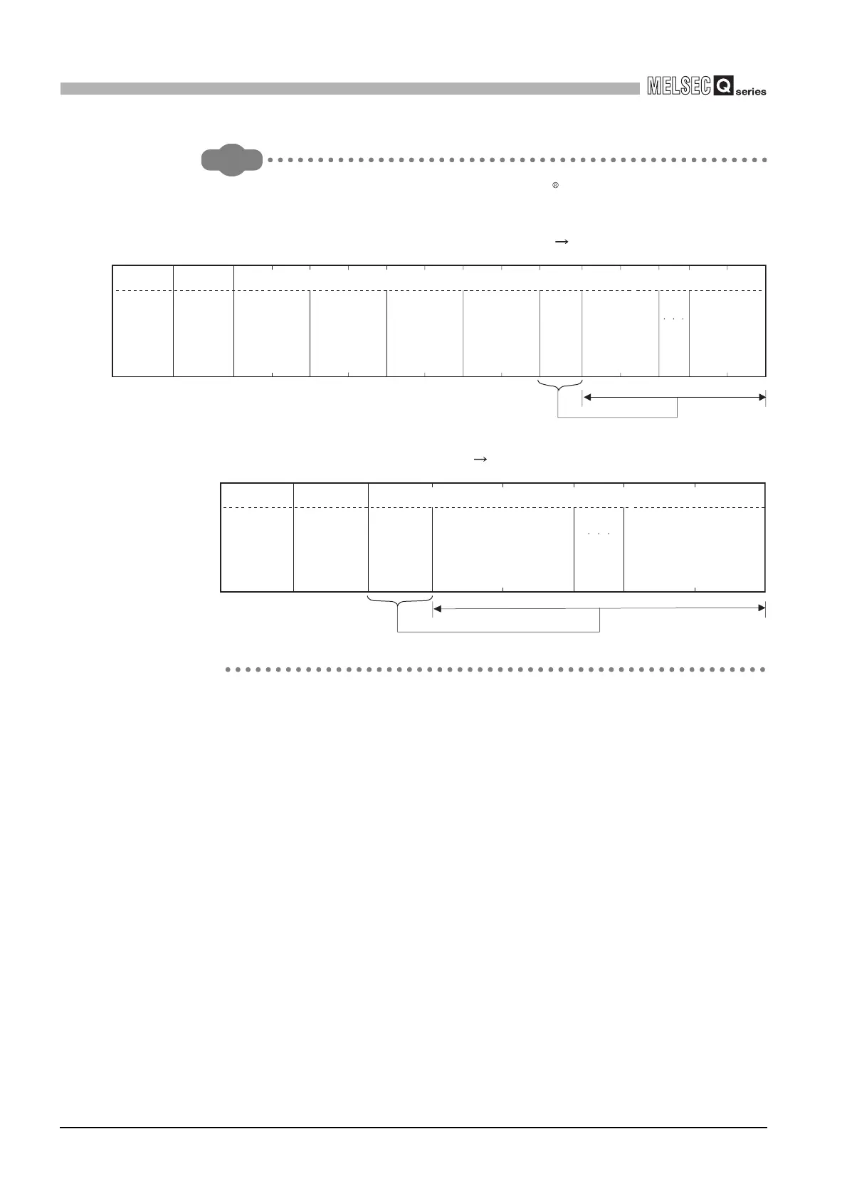
In this sample program, the following MODBUS frames are used for the
communication with the slave.
Request message format (Master (QJ71MB91) Slave)
Response message format (Slave Master (QJ71MB91))
Data
(H) (L) (L) (L) (L) (L)(L)
Address field
Function code
Target station
No.
(01
H
)
Function code
(17
H
)
Read head
holding register
number
(2AF7
H
)
Read points
n
(0064
H
)
Write head
holding register
number
(01F3
H
)
Number of
write points
m
(0020
H
)
Number
of bytes
m x 2
(0040
H
)
Write device
data
1
(value of W0000)
Write device
data
m
(value of W001F)
(Number of bytes m x 2)
(H)
(H) (H)
(H)
(H)
Data
(L) (L)
Address field Function code
Host station No.
(01
H)
Function code
(17H)
(Number of bytes n x 2)
Number
of bytes
n x 2
(C8H)
Read device data
1
(value of 411000)
Read device data
n
(value of 411099)
(H)
(H)
 Loading...


