10
DEDICATED INSTRUCTIONS
10.3 Z(P).MBREQ
10 - 16
9
PROGRAMMING
10
DEDICATED
INSTRUCTIONS
11
TROUBLESHOOTINGAPPENDICESINDEX
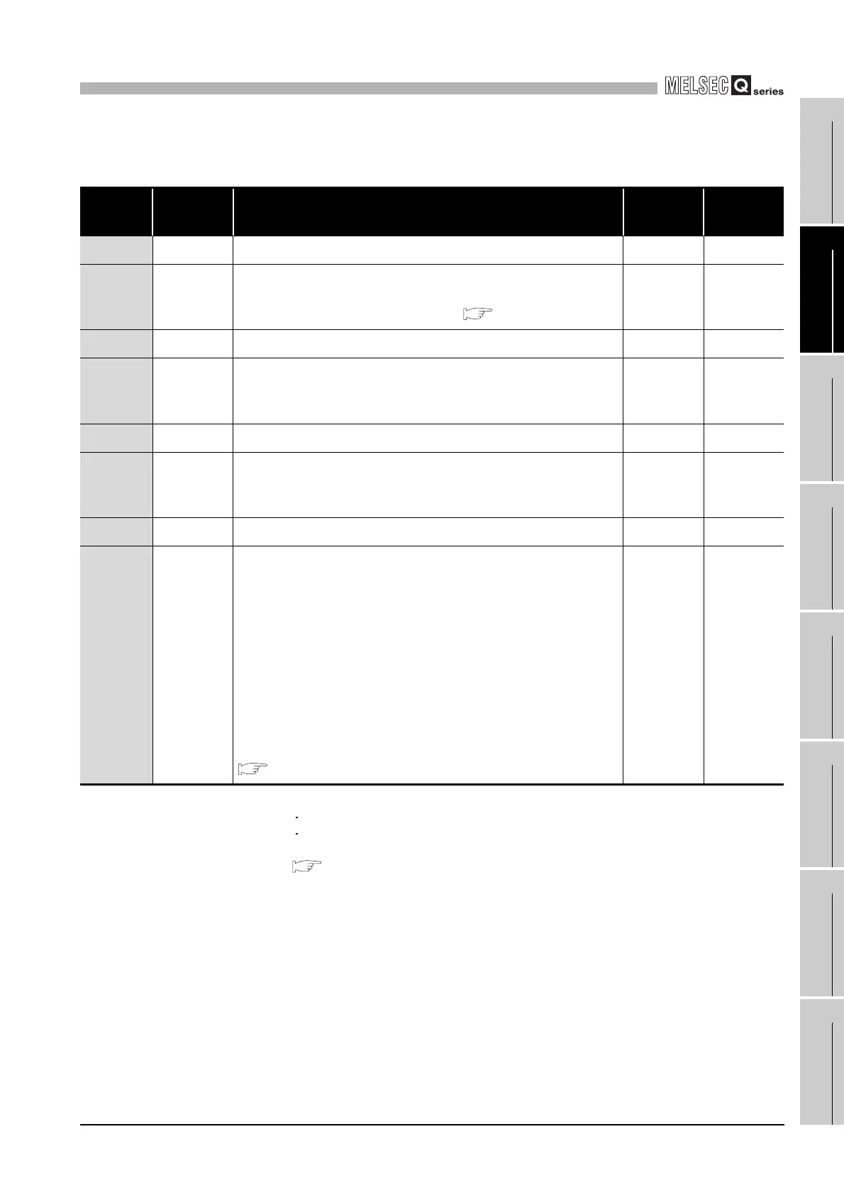
(2) Control data
* 1 The setting side is as described below.
User : Data are set by the user before dedicated instruction execution.
System: The programmable controller CPU stores the result of dedicated instruction execution.
* 2 For function codes that can be broadcast, refer to the following:
Section 4.1
* 3 When specifying a value of 32768 (8000
H) or more in a sequence program, set the value in
hexadecimal.
Table10.10 Control data of the MBREQ instruction
Device Item Setting data
Setting
range
Setting
side
*1
(S1)+0 - Specify 0. 0User
(S1)+1
Completion
status
The status of the instruction completion is stored.
0 : Normal completion
Other than 0: Error completion (error code) ( Section 11.4.3)
-System
(S1)+2 - Specify 0. 0User
(S1)+3 Channel
Specify the target channel.
1: RS-232
2: RS-422/485
1, 2 User
(S1)+4 - Specify 0. 0User
(S1)+5
Target station
No.
Specify the station number of the target slave.
0 : Broadcast
*2
1 to 247: Slave station No.
0 to 247 User
(S1)+6 - Specify 0. 0User
(S1)+7
Response
monitoring
timer value/
Broadcast
delay value
[Response monitoring timer value (Target station No. is 1 to 247)]
Specify the time for monitoring a response from the target device (slave).
(Unit: 10ms)
0 : 30 seconds
2 to 65535: Set value (Response monitoring timer value = set value x 10ms)
[Broadcast delay value (Target station No. is 0)]
Specify the wait time after broadcast transmission. (Unit: 10ms)
0 : 400ms
2 to 65535: Set value (Broadcast delay value = set value x 10ms)
For details on the Response monitoring timer value/Broadcast delay value,
refer to the following.
Section 7.2.1 (4)
0
2 to 65535
*3
User
 Loading...


