10
DEDICATED INSTRUCTIONS
10.4 ZP.UINI
10 - 32
9
PROGRAMMING
10
DEDICATED
INSTRUCTIONS
11
TROUBLESHOOTINGAPPENDICESINDEX
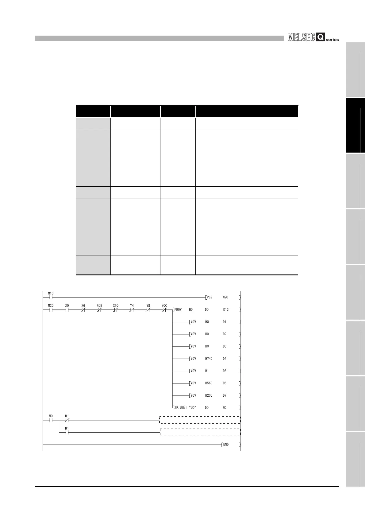
(6) Program example
The program introduced in this section changes the intelligent function module switch
settings to the following.
The I/O signals of the QJ71MB91 are X/Y00 to X/Y1F.
Switch No. Description Default Reference
Switch 1 CH1 Mode Setting 0000H Master function
Switch 2
CH1 Communication
speed/transmission
setting
0740H
Communication speed: 19200bps
Data bit: 8
Parity bit presence: Present
Even/odd parity: Even
Stop bit: 1
Frame mode: RTU mode
Online change: Enable
Switch 3 CH2 Mode setting 0001H Slave function
Switch 4
CH2 Communication
speed/transmission
setting
0560H
Communication speed: 9600bps
Data bit: 8
Parity bit presence: Present
Even/odd parity: Even
Stop bit: 1
Frame mode: ASCII mode
Online change: Enable
Switch 5
CH1/CH2 Station No.
setting
0200H CH1: Station No. 0, CH2: Station No. 2
Figure 10.20 UINI instruction program example
Processing for normal completion
Processing for error completion
Dedicated instruction start command
is changed to pulses.
Control data is cleared to "0".
Completion status is cleared to "0".
Execution type is specified.
CH1 Mode Setting (Switch 1)
CH1 Communication speed/
transmission setting (Switch 2)
CH2 Mode setting (Switch 3)
CH2 Communication speed/
transmission setting (Switch 4)
CH1/CH2 Station No. setting (Switch 5)
Execution of dedicated instruction
Normal completion (M0: ON, M1: OFF)
Error completion (M0: ON, M1: ON)
Instruction
completion
 Loading...


