3
SPECIFICATIONS
3.3 RS-422/485 Interface Specification
3.3.3 Precautions when transferring data using RS-422/485 line
3 - 9
1
OVERVIEW
2
SYSTEM
CONFIGURATION
3
SPECIFICATIONS
4
MODBUS(R) STANDARD
FUNCTIONS
5
FUNCTION
6
PRE-OPERATIONAL
PROCEDURES AND
SETTINGS
7
PARAMETER SETTING
8
UTILITY PACKAGE
(GX Configurator-MB)
(2) RS-422/485 interface operation
(a) RS-422/485 interface configuration
For RS-422/485 interface, the configuration of driver (send)/receiver (receive)
component of the QJ71MB91 is as shown in the following diagram.
* 1 The "output control input" (also referred to as send gate) of the driver (send) component
determines whether to output data externally from SDA, SDB.
(b) RS-422/485 interface operation
When the "output control input" in the above figure is ON, the impedance status is
low (data transmittable).
In addition, when the "output control input" is OFF, the impedance status is high
(data not transmitted).
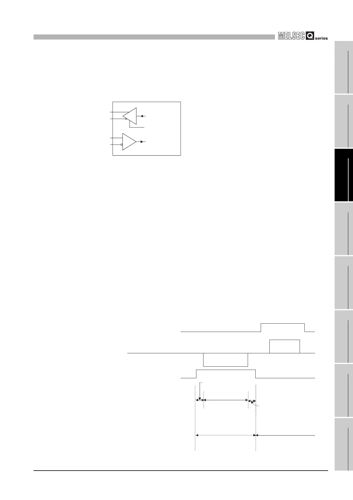
(c) QJ71MB91 transmission start timing, transmission process complete timing
• Transmission start timing
After releasing the high impedance status indicated in above (a) and (b), and
outputting two or more character data during data transmission, output the
actual data.
• Transmission process complete timing
Data transmission time for data of 1 bit or less is required as the H/W gate
OFF time to complete the transmission process (high impedance status) after
finishing data transmission.
(Transmission speed set in the QJ71MB91 is targeted.)
Figure 3.4 RS-422/485 interface configuration
Figure 3.5 Transmission process complete timing
Send data
SDR
SDB
RDA
RDB
Receiver
Driver
Output Control Input (*
1
)
Receive data
Data
Data
(Output control input)
(Output control input)
Target device side
QJ71MB91 side
Outputs a mark with
2 characters or more
Data transmission
time range
H/W gate OFF time
(Refer to explanation above)
OFF time range of
output control input
(High impedance status)
QJ71MB91 can receive data.
ON time range of output
control input
(Low impedance status)
QJ71MB91 can send data.
 Loading...


