3
SPECIFICATIONS
3.5 Applications and Assignment of Buffer Memory
3.5.1 Buffer memory list
3 - 17
1
OVERVIEW
2
SYSTEM
CONFIGURATION
3
SPECIFICATIONS
4
MODBUS(R) STANDARD
FUNCTIONS
5
FUNCTION
6
PRE-OPERATIONAL
PROCEDURES AND
SETTINGS
7
PARAMETER SETTING
8
UTILITY PACKAGE
(GX Configurator-MB)
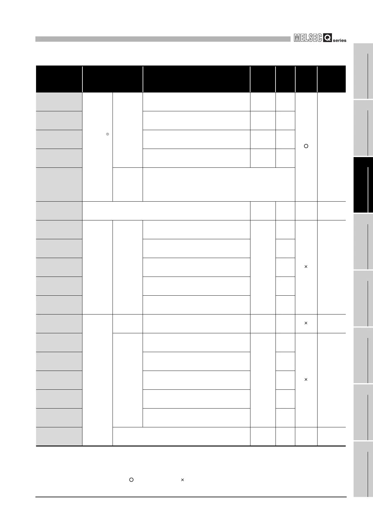
* 1 Indicates whether the reading (Read)/writing (Write) from the sequence program is enabled or
disabled.
R: Readable W: Writable
* 2 Indicates whether setting on GX Configurator-MB is enabled or disabled.
: Setting enabled : Setting disabled
(Continued on next page)
Table3.4 Buffer memory list (Continued)
Address Application Name
Initial
value
Read/
Write
(*1)
Initial
setting
(*2)
Reference
09C0
H
(2496)
MODBUS
device
assignment
parameter
Holding
register
assignment
1
Device code 0
H
R/W
Section
7.3.1
09C1
H
(2497)
Head device number 0
H
R/W
09C2
H
(2498)
Head holding register number 0
H
R/W
09C3
H
(2499)
Assignment points 0
H
R/W
09C4
H
to 09FF
H
(2500 to 2559)
Holding
register
assignment
2 to 16
(Same as in holding register assignment 1)
0A00
H
to 0BFF
H
(2560 to 3071)
System area (use prohibited) - - - -
0C00
H
(3072)
Setting
status
Intelligent
function
module
switch
setting
status
Switch 1: CH1 operation mode setting status
Intelligent
function
module
switch
status
R
Section
6.6, 11.2
0C01
H
(3073)
Switch 2: CH1 transmission setting status R
0C02
H
(3074)
Switch 3: CH2 operation mode setting status R
0C03
H
(3075)
Switch 4: CH2 transmission setting status R
0C04
H
(3076)
Switch 5: CH1/CH2 Station No. setting status R
0C05
H
(3077)
Operating
status
Module
status
LED ON status 0
H
R
Section
6.3, 11.2
0C06
H
(3078)
Intelligent
function
module
switch
operating
status
Switch 1: CH1 operation mode status
Intelligent
function
module
switch
status
R
Section
10.4
0C07
H
(3079)
Switch 2: CH1 transmission status R
0C08
H
(3080)
Switch 3: CH2 operation mode status R
0C09
H
(3081)
Switch 4: CH2 transmission status R
0C0A
H
(3082)
Switch 5: CH1/CH2 Station No. status R
0C0B
H
to 0C12
H
(3083 to 3090)
System area (use prohibited) - - - -
 Loading...


