3
SPECIFICATIONS
3.5 Applications and Assignment of Buffer Memory
3.5.1 Buffer memory list
3 - 23
1
OVERVIEW
2
SYSTEM
CONFIGURATION
3
SPECIFICATIONS
4
MODBUS(R) STANDARD
FUNCTIONS
5
FUNCTION
6
PRE-OPERATIONAL
PROCEDURES AND
SETTINGS
7
PARAMETER SETTING
8
UTILITY PACKAGE
(GX Configurator-MB)
* 1 Indicates whether the reading (Read)/writing (Write) from the sequence program is enabled or
disabled.
R: Readable W: Writable
* 2 Indicates whether setting on GX Configurator-MB is enabled or disabled.
: Setting enabled : Setting disabled
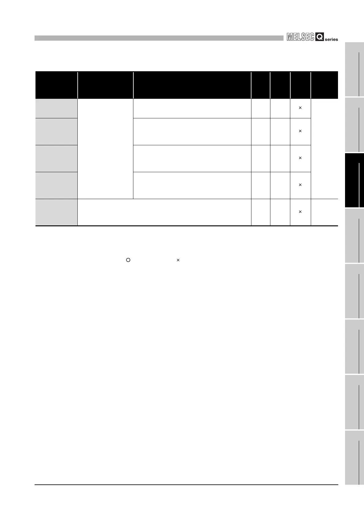
Table3.4 Buffer memory list (Continued)
Address Application Name
Initial
value
Read/
Write
(*1)
Initial
setting
(*2)
Reference
1000
H
to 1FFF
H
(4096 to 8191)
Automatic
communication function
buffer
CH1 Automatic communication function buffer input
area
0
H
R
Section
5.2.1
2000
H
to 2FFF
H
(8192 to
12287)
CH2 Automatic communication function buffer input
area
0
H
R
3000
H
to 3FFF
H
(12288 to
16383)
CH1 Automatic communication function buffer output
area
0
H
R/W
4000
H
to 4FFF
H
(16384 to
20479)
CH2 Automatic communication function buffer output
area
0
H
R/W
5000
H
to 5FFF
H
(20480 to
24575)
User free area 0
H
R/W
Section
7.3.3
 Loading...


