Sec 1: 8-20 Disassembly/Reassembly Procedures: Serviceable Components of the Main Sub-Assemblies
8.7.9 Removal of the Control Top Assembly (F)
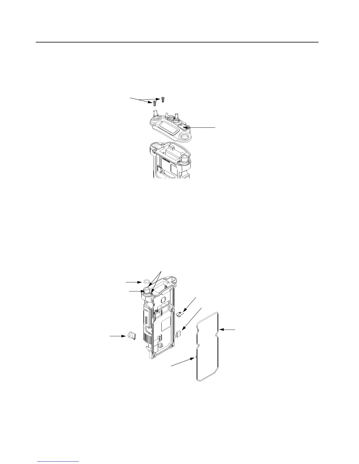
i. Use a Torx Plus IP8 bit to remove the two Control Top Screws (44). See Figure 8-28.
NOTE: Ensure the Control Top flex is disconnected from the VOCON Board (D) to prevent
damage to the flex or connector.
Figure 8-28. Remove Control Top Assembly
ii. Gently separate the Control Top Assembly (F) from the Main Chassis Assembly (E).
NOTE: Place the Control Top Assembly (F) and the remaining Main Chassis Assembly (E)
on an ESD safe surface free from debris.
8.8 Serviceable Components of the Main Sub-Assemblies
8.8.1 Servicing Main Chassis Assembly (E)
Figure 8-29. Serviceable Components – Main Chassis Assembly
Control Top Assembly (F)
Control Top Screws (44)
Main Seal (50)
Chassis Ground Contact (18)
Universal Connector Insert (17)
O-Ring (16)
NOTE: For assembly, ensure the key feature
is aligned as shown.
RF Coax Cable (20)
Screws (44)
Coin Cell Pad (19)
 Loading...


