Disassembly/Reassembly Procedures: Serviceable Components of the Main Sub-Assemblies Sec 2: 8-21
8.8 Serviceable Components of the Main Sub-Assemblies
8.8.1 Servicing Main Chassis Assembly (E)
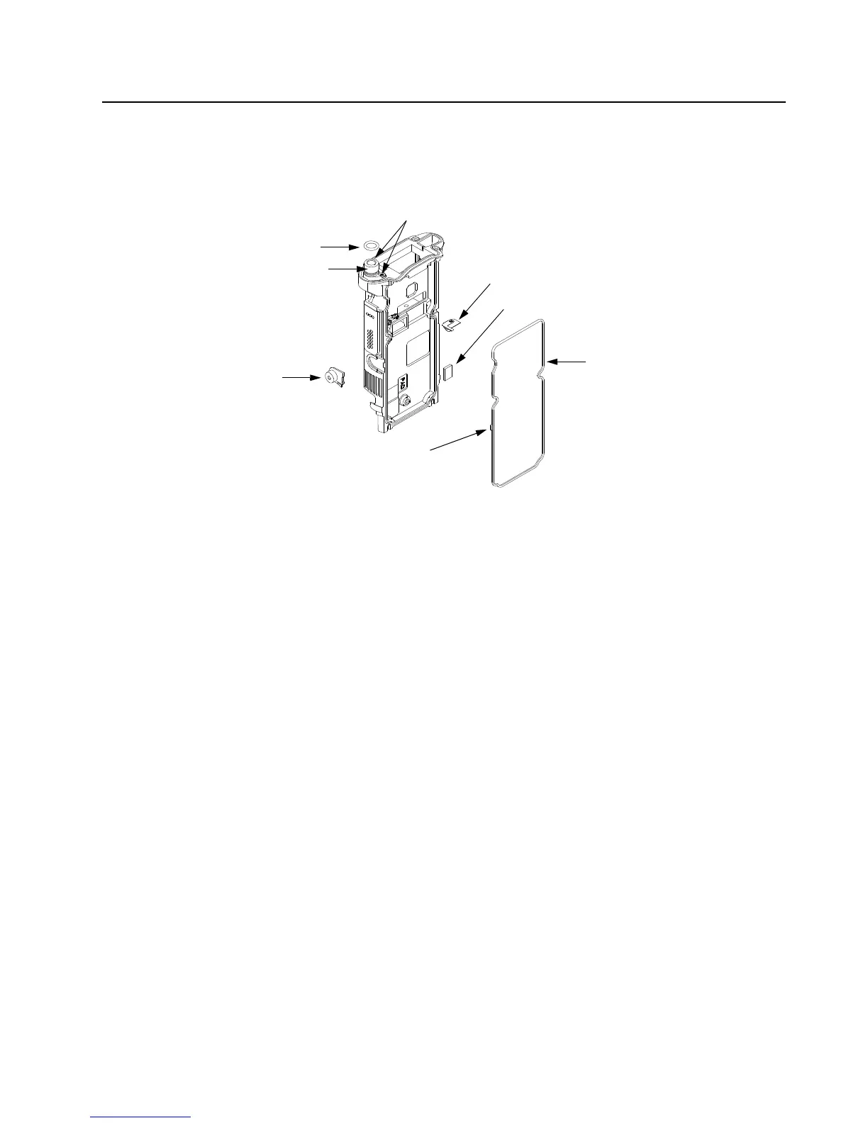
Figure 8-30. Serviceable Components – Main Chassis Assembly
8.8.1.1 Servicing Coin Cell Pad:
1. Complete steps from Section 8.7.1. through Section 8.7.9. of section 8.7 on page 2:8-13.
2. Carefully peel off the pad.
3. Use the Black Stick to help remove any difficult sections of the pad(s).
4. Clean the area once the pad is removed to ensure it is free of adhesive and debris.
5. Peel the liner off the new pad and place in the respective location.
6. Apply slight pressure to set the adhesive.
8.8.1.2 Servicing Universal Connector Insert:
1. Complete steps from Section 8.7.1. through Section 8.7.4. of section 8.7 on page 2:8-13.
2. Ensure the locking tab is pressed and carefully slide the Universal Connector Insert (17) with
the Black Stick from the Main Chassis Assembly (15) as shown in Figure 8-30.
3. Press the new Universal Connector Insert until it is fully seated and the lock tab is engaged
on the chassis.
8.8.1.3 Servicing Antenna O-ring:
1. Complete steps from Section 8.7.1. through Section 8.7.9. of section 8.7 on page 2:8-13.
2. Remove the O-ring (16) with the Black Stick.
3. Reinstall the O-ring by rolling it over the threaded portion of the antenna hub until it sets in its
groove.
NOTE: Ensure the O-ring is not twisted.
Main Seal (54)
Chassis Ground Contact (18)
Universal Connector Insert (17)
O-Ring (16)
NOTE: For assembly, ensure the key feature
is aligned as shown.
RF Coax Cable (20)
Screws (44)
Coin Cell Pad (19)
 Loading...


