Disassembly/Reassembly Procedures: Serviceable Components of the Main Sub-Assemblies Sec 1: 8-23
8.8.3 Servicing Knobs and Top Bezel Assembly (G)
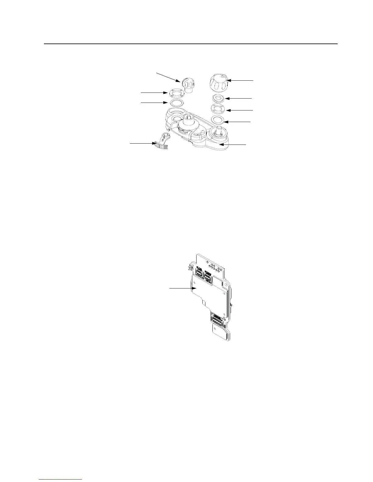
Figure 8-32. Top Bezel Assembly
8.8.3.1 Secure Lever
1. Complete steps from Section 8.7.8. of section 8.7 on page 1:8-13.
2. Pull the Secure Lever (25) straight out of Top Bezel Assembly (24) as shown in Figure 8-32.
3. Insert the lever's arm into the bezel's slot.
NOTE: All serviceable components on the Top Bezel Assembly are shown in Figure 8-32
8.8.4 Servicing VOCON Board Assembly (D)
Figure 8-33. VOCON Board Assembly
NOTE: There are no serviceable components on the VOCON Board Assembly.
Volume Knob (29)
Torque Adder (30)
Volume Spanner Nut (31)
Frequency Knob (28)
Antenna Spanner Nut (27)
Antenna Washer (26)
Volume Washer (32)
Secure Lever (25)
Top Bezel Assembly (24)

 Loading...


