Disassembly/Reassembly Procedures: Serviceable Components of the Main Sub-Assemblies Sec 2: 8-27
8.8.6.4 Servicing the Main Lens
NOTE: Prior to Lens removal, Color Display must be removed (See Section 8.8.6.3 on page
2:8-26).
1. Remove the main Lens (7) carefully and slowly with the Black Stick.
NOTE: To ease the breaking of the adhesive bond, place Back Chassis in freezer.
2. Clean the area once the Lens is completely removed to ensure it is free of adhesive and
debris.
3. Peel the liner off of the adhesive side of the new Lens and place it centered left to right in the
lens pocket of the Back Chassis assembly. Bias it upwards against the horizontal surface.
4. Press the Lens down.
5. Ensure the adhesive shows no sign of air entrapments.
NOTE: There are no other serviceable components on the Back Chassis Assembly.
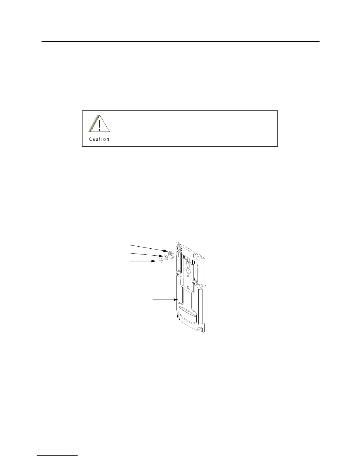
8.8.7 Servicing Back Chassis Assembly (N) – Top Display Version
Figure 8-37. Back Chassis Assembly (Top Display Version)
Over prying may damage the lens.
Back Chassis Assembly (52)
Mic Mesh (6)
Mic Membrane (5)
Mic Boot (4)

 Loading...


