Disassembly/Reassembly Procedures: Serviceable Components of the Main Sub-Assemblies Sec 2: 8-25
8.8.4.3 Back up Battery
1. Complete steps from Section 8.7.1. through Section 8.7.7. of section 8.7 on page 2:8-13.
2. Remove the battery with the Black Stick.
NOTE: Make sure the positive side is facing upwards.
3. Press the new battery into the battery carrier until it is secured and fully snapped into place.
NOTE: There are no serviceable components on the RF Board Assembly.
8.8.5 Servicing of Expansion Board Assembly
1. Complete steps 8.7.1 through 8.7.3 of section 8.7 on page 2:8-13.
Figure 8-35. Expansion Board Assembly
NOTE: There are no serviceable components on the Expansion Board Assembly.
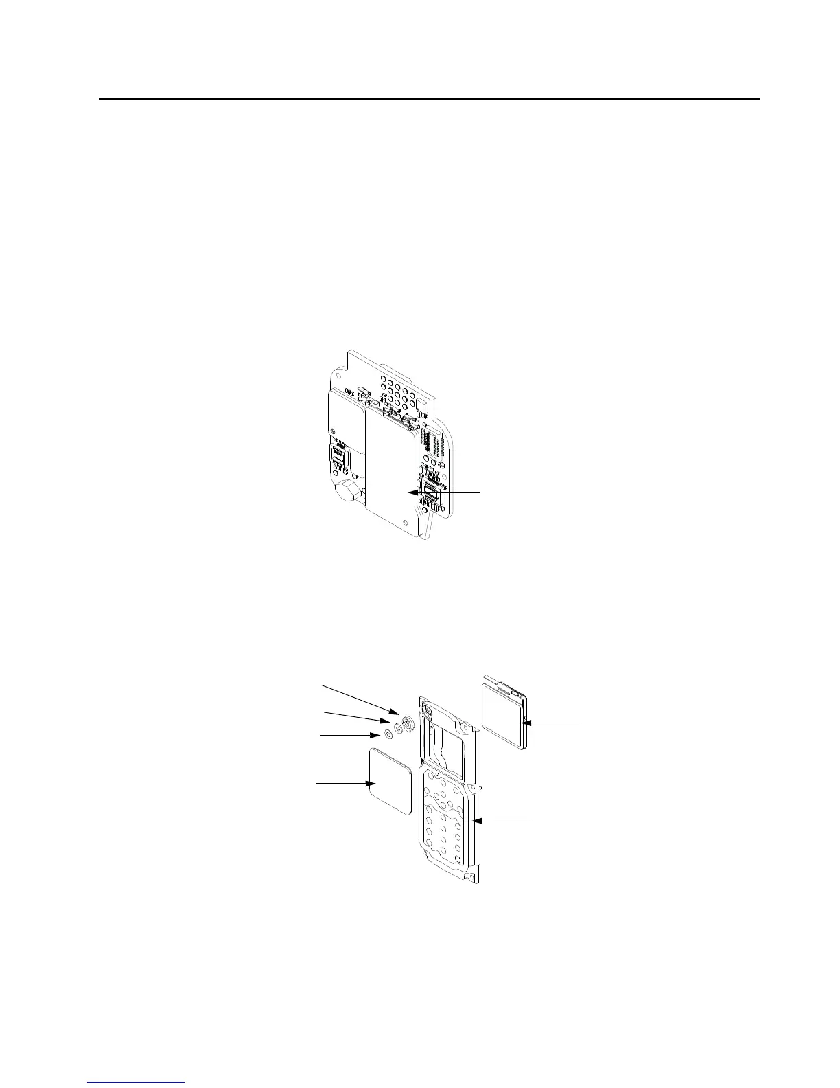
8.8.6 Servicing Back Chassis Assembly (B) – Dual Display Versions
1. Complete steps 8.7.1 through 8.7.5 of section 8.7 on page 2:8-13.
Figure 8-36. Back Chassis Assembly (Dual Display Versions)
NOTE: Take care not to damage the Color Display during disassembly.
Expansion Board Assembly (H)
Color Display (8)
Back Chassis Assembly (3)
Mic Mesh (6)
Lens (7)
Mic Boot (4)
Mic Membrane (5)

 Loading...


