Disassembly/Reassembly Procedures: Radio Reassembly Sec 2: 8-37
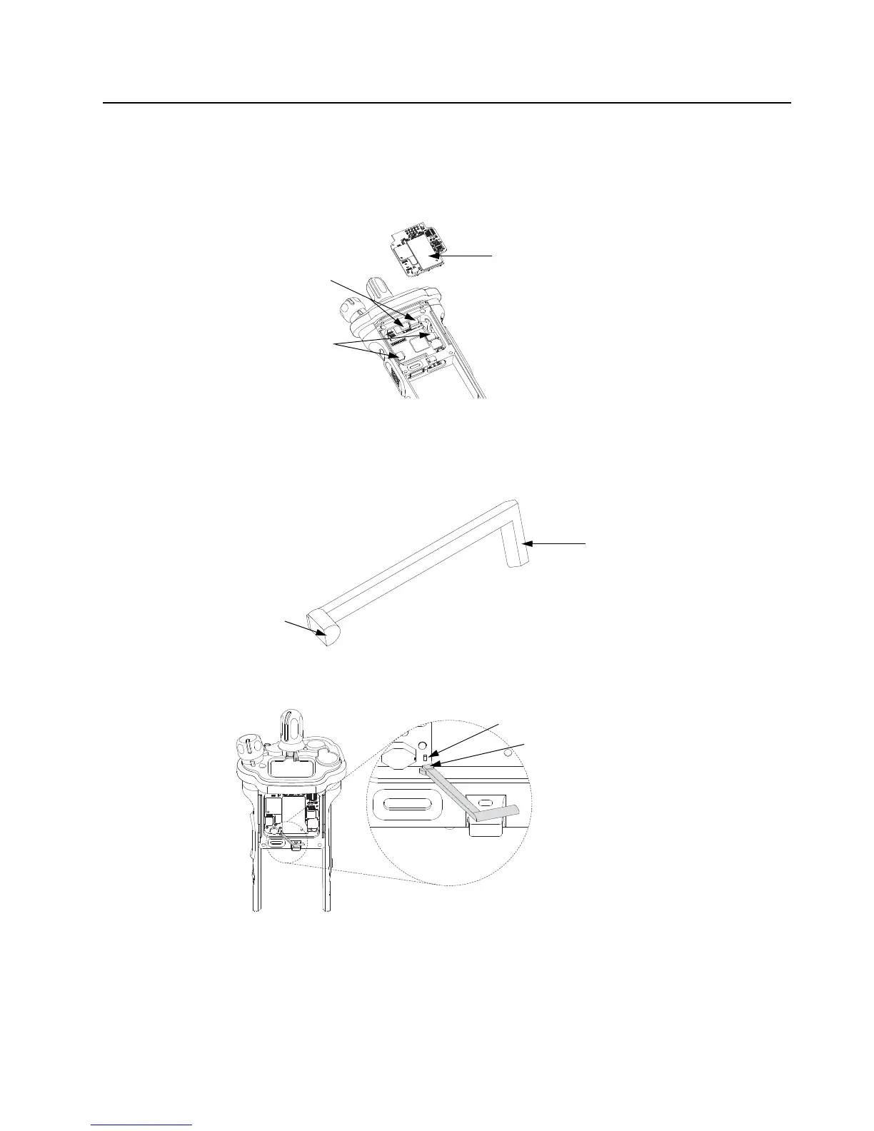
5. Plug the Expansion Board Assembly (H) to the VOCON Board Assembly (D) as shown in
Figure 8-50. Make sure the connector is fully engaged.
6. Connect the two Flex Connectors to their pairing connectors on the right and left sides of the
Expansion Board Assembly as shown in Figure 8-50.
Figure 8-50. Insert Flex Connectors
7. Insert the rounded portion of the Expanded Board Support (61) into the opening of the
vacuum test compartment on the expanded side as shown in as shown in Figure 8-52.
Figure 8-51. Expander Board Support (61)
Figure 8-52. Insert Expander Board Support
8. Ensure the Rounded portion of the Expander Board Support is secure properly before
rotating the Expander Board Support towards the Antenna Coax Connector.
9. Slide the Locking Feature of the Expander Board Support between the Antenna Coax
connector and the Chassis Wall.
Flex Connectors
Expansion Board Assembly (33)
Control Top Support Pads
Rounded Portion
Locking Feature Portion
Capacitor to avoid
Rounded portion of
Expander Board Support

 Loading...


